Printer Friendly (PDF)
 Decarbonization does not always automatically become electrification. The enterprising engineer will first look at diverse ways to reduce the carbon use. Here is an example of using a double wall heat exchanger to remove the heat from the condenser water to pre-heat the cold service water before it enters the water heaters.
Water Heater Design Example
In domestic water heaters we normally design for a supply temperature of 40⁰F from the municipal system. This is about the coldest water we might expect in the dead of winter. That supply water will be between 50⁰F and 55⁰F in the summer.
To make the numbers realistic, I will use a system with three Aerco Innovation 1060 tankless water heaters, with one of them standby. Assume a supply water temperature of 120⁰F with no storage. Each heater will have a capacity of 29 GPM from 50⁰F to 120⁰F. This is the system used in the Aerco Elder-Care case study on their website.
We know the load will not be at 100% very often if at all. In would be reasonable and conservative to assume there will be a 25% load for about 6 hours a day. During those times we could have a load of 490,000 BTUH (14 GPM x (120⁰F – 50⁰F) x 500). If we can change the supply temperature to 85⁰F, the load will drop to 245,000 BTUH. A savings of 50% of the load and the carbon produced by the gas appliances.
Condenser Water has Heat to Give. Service Water has Heat to Gain.
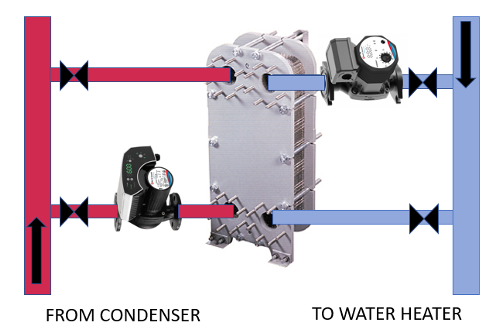
In Michigan and Ohio, we normally design the condenser water systems for temperatures in the range of 85⁰F from the cooling tower and 95⁰F back to the tower. The 95⁰F water has heat to give. We could use a Bell & Gossett GPX double wall plate style heat exchanger to capture some of the condenser water heat. We will use a one pipe primary system on both sides of the heat exchanger.
For this example, I will use 14 GPM of the design 50 GPM flow on the domestic hot water side. I selected the 14 GPM for a couple of reasons. Designing for the total load of 59 GPM will make the equipment much more expensive for a load that will not happen often. The 14 GPM load is a reasonable flow rate to assume for many hours per day considering showers and an active kitchen for three meals a day.
The other reason is first cost. This load keeps us in lower cost equipment. Through an iterative process I found the first cost of equipment reasonable at this flow rate. We are doing this to reduce the carbon footprint, but some payback analysis will be expected.
This heat exchanger load will be: 14 GPM of domestic cold water from 50⁰F to 85⁰F using 49 GPM of condenser water 95⁰F to 85⁰F. The tower water system would be much larger than 49 GPM, so we are using a one pipe primary with a 49 GPM ECM pump to take a portion of the water leaving the condenser.
Simple Control of the Pumping System
This system will only work when there is a load on the domestic hot water system and the cooling system condenser is also on. The pumps in this carbon reducing energy saving system will turn on when both loads are active. If there is domestic hot water load, the Aerco Innovation tankless heater will be on and can close a set of contacts to indicate it. The building management system could also close a set of contacts when the chiller is active. The two sets of contacts in series will activate the pumps.
I chose the small Bell & Gossett ECM Ecocirc® model 20-18 SS for the service water side and the B&G Ecocirc for the tower side water. Both are ECM highly efficient pumps. They are variable speed and will not require any other control.
Energy Savings As Well As Carbon Reduction.
This opportunity will clearly reduce the carbon emissions from gas fired appliances. The question of the cost to do it will always be there. This example system will use a B&G GPX double wall heat exchanger series P20DW with the two ECM pumps.
This example system will save 245,000 BTUH on domestic water load for the estimated 6 hours per day the flow rate is 14 GPM or more. There will also be some savings when the flow rate is less than 14 GPM.
There is more. We are also saving the 245,000 BTUH on the cooling side by reducing the inlet temperature to the cooling tower.
The key is recognizing the building type with an expected hot water load for many hours per day, coupled with a cooling tower system. Then, work with your B&G representative to choose the load and equipment to keep the first cost reasonable. The payback for this carbon reduction will be much less than 3-4 years. The heat exchanger is only 2’ x 2’ x 3’ so it will not use much space.
You may be questioning my use of pumps in this system. Why not just flow the water from the city though the exchanger and get what we can get without pumps? The answer will be the subject of the next R. L. Deppmann Monday Morning Minutes.