Printer Friendly (PDF)
 Open cooling tower pumps are traditionally operated as constant speed. When balanced, the extra pump head or over-heading is throttled across the discharge balance valve or triple duty valve. This throttled valve is wasting energy and utility costs. Today many utilities are offering rebates to add drives to these open cooling tower systems. How does the balance contractor set the speed of the drive?
Pump Head Calculations in Open Systems
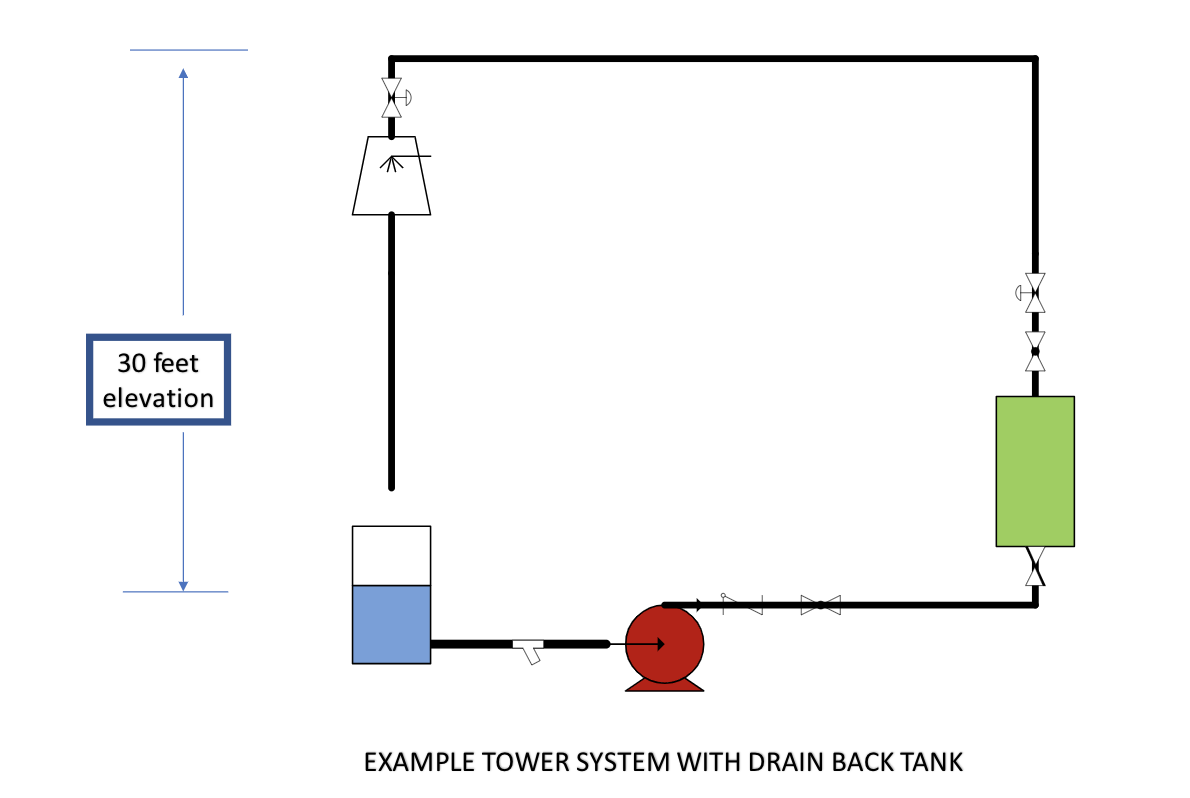
Above is an example system. This is an open cooling tower with a drain back tank for winter operation. If the chiller system shuts down, all the tower water flows back into the tank in the building. There is no tower pan which would hold water and possibly freeze. The pump capacity as scheduled is 1800 GPM at 80 feet and 1750 RPM constant speed.
When an engineer selects the pump head for an open system, they add three factors together. The first factor is the variable head loss which is sometimes called the friction loss. This is the pressure drop at design flow rate through pipe, valves, fittings, and equipment. The second factor is the lift. The is the “open” part of the system. In our example system above, the lift is 30 feet. The third factor is the ever-present safety factor.
This third factor can include an amount for future scaling; round-up additions to head; additions caused by using a general pipe friction loss such as 4 feet/100 feet vs. the actual pressure drop; an amount added to the condenser pressure drop in case another brand chiller is purchased; and, finally, a number added as a percentage of head for safety. It is very easy to oversize a pump.
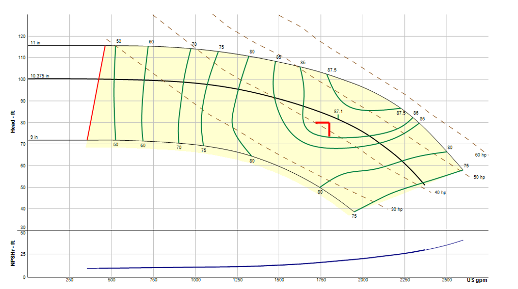
Below is the pump curve.
The Lift is Not Subject to the Second Pump Affinity Law
The lift or elevation does not change whether we are flowing 1 GPM or 1800 GPM. Until the pump produces the lift, no flow occurs. The lift is not subject to the second affinity law.
What happens in the example system if we forget this important rule? Look at the capacity and form a system curve. If we assume no lift, the curve looks like this.
The system curve would look familiar to us.
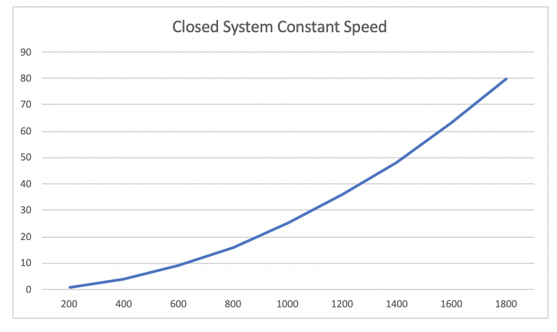
If this is the system curve, what happens when the condenser is operating at 900 GPM? The pump is doing 20 feet of head. This is not enough pressure to lift the water up so we can start flowing. Something is wrong. This is not the right system curve!
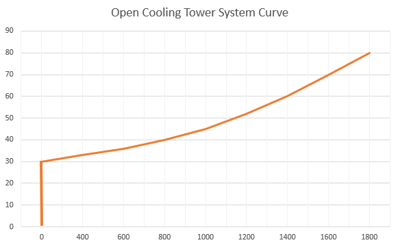
When doing a system curve for an open system, we must separate the variable head from the constant head. Remember, no flow occurs until the lift is met. The data looks like this.
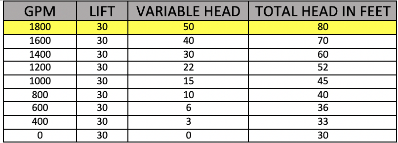
The system curve looks like this.
Adding a VFD to a Cooling Tower Pump
The discharge triple duty valve of this constant speed system is throttled. There is an extra 15 feet across the triple duty when compared to the pressure drop with the valve wide open. Now we are going to put a VFD or variable speed drive on the pump. We will reduce the speed and open the triple duty to 100%.
At 1750 RPM, when the triple duty valve is throttled, we have a pump operating at 1800 GPM at 80’. When the triple duty valve is opened, the pump runs out to about 2000 GPM at 73 feet. This creates a new system curve. The curve starts at 0 GPM at 30 feet and goes through the point 2000 GPM at 73 feet. If we look at the pump with variable speed curve and a system curve shown above, we can choose the correct speed at 1800 GPM.
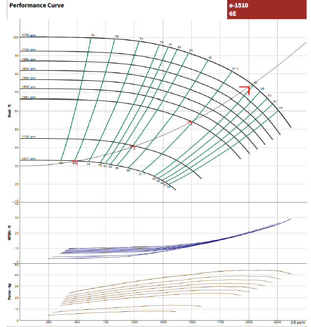
We can see that the intersection of the pump curve and the system curve falls at 1600 RPM. This is the maximum speed that the pump would be set at with a variable speed drive.
This analysis is similar in closed systems with a control head. We will look at that in the next R. L. Deppmann Monday Morning Minutes.