Printer Friendly (PDF)
 Pressure relief valve sizing for heating systems is well documented by ASHRAE, boiler codes, and product manufacturers such as Bell & Gossett. Relief valve sizing methods for closed chilled water systems are not as easy to find. How do you size this small insurance policy, the chilled water pressure relief valve?
The Need for a Chilled Water Pressure Relief Valve
Every closed hydronic system must have a compression or expansion tank. One purpose of the tank is to keep the system pressure under control. The pressure relief valve’s job is to relieve the pressure of a waterlogged tank or if the bladder fails or the tank is isolated from the system or the unexpected happens. To increase the closed chilled water pressure with the pump off, we must add heat.
Where Does the Heat Come From?
The heat in a chilled water system comes from ambient conditions. When the chiller shuts down at the end of the season or due to a failure, the air surrounding the pipe and outside air blowing across coils adds BTUs to the water. These BTUs cause a temperature rise which in turn tries to raise the pressure in this closed hydronic system.
![]()
BTUH Transfer from the Piping System
The first concern is simply the heat gained by the surrounding air. Let’s assume the pipe insulation is per ASHRAE 90.1- 2013 standards which is also the Michigan Energy Code. Table 6.8.3.2 tells us the conductivity should be 0.21-0.27 BTU-in/h-°F-FT2. If I use the worst case of 0.27 and assume I have a mile of 8” pipe, the total is about 700,000 BTUH. A B&G model 790-100 pressure relief valve is ¾” and has a BTUH capacity of over 2 million BTUH! This relief valve would easily meet the need.
BTUH Transfer from the Coils
The BTUH added to the piping system will follow the formula:
BTUH = U x A x LMTD
“A” is the heat transfer surface of the coil. U is the rate of heat transfer, and LMTD is the log mean temperature difference between the air and water in the Air Handling Unit (AHU) coil.
The area of the coils is constant. The U value will remain constant if we assume the pumps and fans are running and the chiller is off. There is a slight change in “U” value as the average temperature changes, but it is negligible for this discussion. So, the LMTD is the factor that will determine the BTUH heat transfer. As the water in the pipe gets warmer, the LMTD drops and the BTUH heat transfer rate drops. So, the worst case will be when the chiller first shuts off.
When the chiller is off and the fans and pumps are on, the water temperature will increase as it passes through the AHU coil. The water will try to expand as the air heats the water. If the expansion tank is missing or damaged, the pressure will build up. The relief valve will then blow to protect the system. How big does the relief valve have to be?
The flow rate passing the coils will cause volume expansion based on the GPM through them. You can think of this as expansion per minute in the expansion tank. Each time the water passes the coils, the average temperature in the system goes up and there is a corresponding attempt to increase the volume. What if the tank cannot solve the expansion problem? We must make sure that the relief valve can relieve the volume expansion per minute to avoid the pressure from building over the working pressure.
An Example
Let’s look at a ridiculous example to make a point. Assume we have a 3,000 ton chilled water system with a 10°F ∆T. Assume the chiller is damaged and offline and the expansion tank is damaged and the fans are blowing and the outside temperature is 100°F and there is no air anywhere in the piping system and the control system safeties have failed. That is a lot of ands! We said it would be ridiculous.
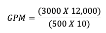
The design flow rate assuming will be 7,200 GPM.
Think of the expansion tank formula. There is the expansion of water minus the expansion of pipe times the system volume. Let’s assume the volume of the system is 7,200 gallons. The 7,200 GPM will experience an attempted volume expansion. Expansion will happen each minute that the 7,200 gallons is heated at the coils.
We mentioned earlier, the heat transfer will be the greatest when the chiller first fails. LMTD will be the greatest when the temperature difference between the water and the 100°F air is the greatest. In fact, the LMTD when the average water temperature is 90°F will be less than 20% of what it was when the average water temperature was 50°F. The heat transfer rate will follow. A lot of words to indicate the heat transfer rate is the greatest in the first minute of this failed system.
We can use the B&G ESP Systemwize program to determine the expansion volume needed in the first minute that the average temperature rises from 50°F to 60°F. If the relief valve opens at 100 PSIG and we assume a start at 60 PSIG, there will be about 10 gallons of expansion attempted per minute.
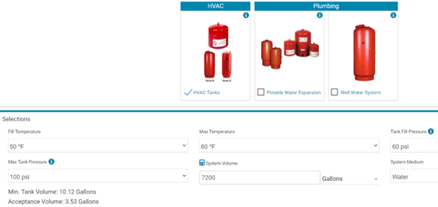
The pressure will not exceed 100 PSIG if the relief valve can dump more than 10 GPM. So which Bell & Gossett ASME relief valve will dump this much flow at 100 PSIG?
B&G ASME Relief Valve Example Problem Solution
We want to relief at least 10 GPM through the B&G relief valve. B&G does not publish the GPM flow rate. We are not even sure if ASME requires them to test for that. The ASME relief valves are designed for heating boilers and rated in BTUH not GPM. That said, we can do calculations because we know the orifice size of the valve is 0.52” and the connections are ¾.”
We assumed a ¾” x 6” nipple at the inlet of the B&G 790 relief valve. On the outlet we assumed a 90⁰ elbow and 6 feet of ¾’ outlet pipe. How much flow rate can we calculate?
The B&G model 790-100-3/4” pressure relief valve does the trick. Here is what we calculated:
| B&G Model | Flow Area | Flow Rate** |
|---|---|---|
| 790-30 | 0.52 | 14 GPM |
| 790-50 | 0.52 | 18 GPM |
| 790-100 | 0.52 | 32 GPM |
** Calculated valves with a K value of 0.52 We used table 65, Theoretical discharge of orifices from an old reference, the Hydraulic Handbook, copywrite 1965, by Colt Industries. We added the friction loss of the piping to these numbers. If you want to do your own calculations there is a great article online, Sizing Pressure Relief Devices by Daniel A Crowl and Scott A. Tipler.
Obviously, if the volume of water in the system doubles, so does the expansion need. We used a large example system. As the volume drops, so does the expansion but the B&G 790-100 is the smallest size ASME section IV relief valve we supply.
B&G may publish their flow rates in the future, but the raw numbers above seem quite conservative.
Another phenomenon often overlooked is that the minute the relief valve blows, another factor comes into play. The B&G makeup pressure reducing valves are designed to keep the makeup water flow rate extremely low. It is simply for makeup. There will be air in the pipe. That air in the pipe will act like an expansion tank.
The Bell & Gossett model 790 ASME Pressure Relief Valve set at the pressure you need should protect most systems we encounter. For more information on the 790 series relief valves, visit Bell & Gossett ASME Relief Valve Model 790.