Printer Friendly (PDF)
 A sediment separator will remove particles down to 20 microns or lower when properly sized and applied. This makes them a great choice in open cooling tower systems when the tower is installed in an area with airborne particulate, sand or other debris. The key word here is “properly applied.”
Before I look at the application of the separators, let’s look at their operation.
What is a Centrifugal Sediment Separator and How does it Work?
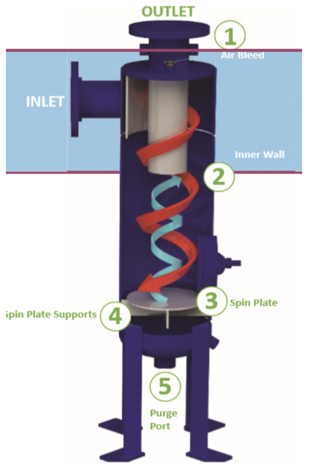
I’ve said this before. Our industry rarely calls a product something too fluffy. In general, if you switch the words around you know what a product does. A centrifugal sediment separator simply separates sediment centrifugally. The Griswold Water Systems series CS shown below uses centrifugal action to move dirt toward a collection area for blowdown.
Griswold Water Systems CCS
This separator requires an internal high velocity to accomplish the separation. This comes with a higher pressure drop range. When selecting the model, the engineer must pay attention to the minimum and design flow rates.
The solids-laden stream of liquid enters the separator tangentially through the entry nozzle and is directed and accelerated by the velocity plate, creating a strong centrifugal force on the flow.
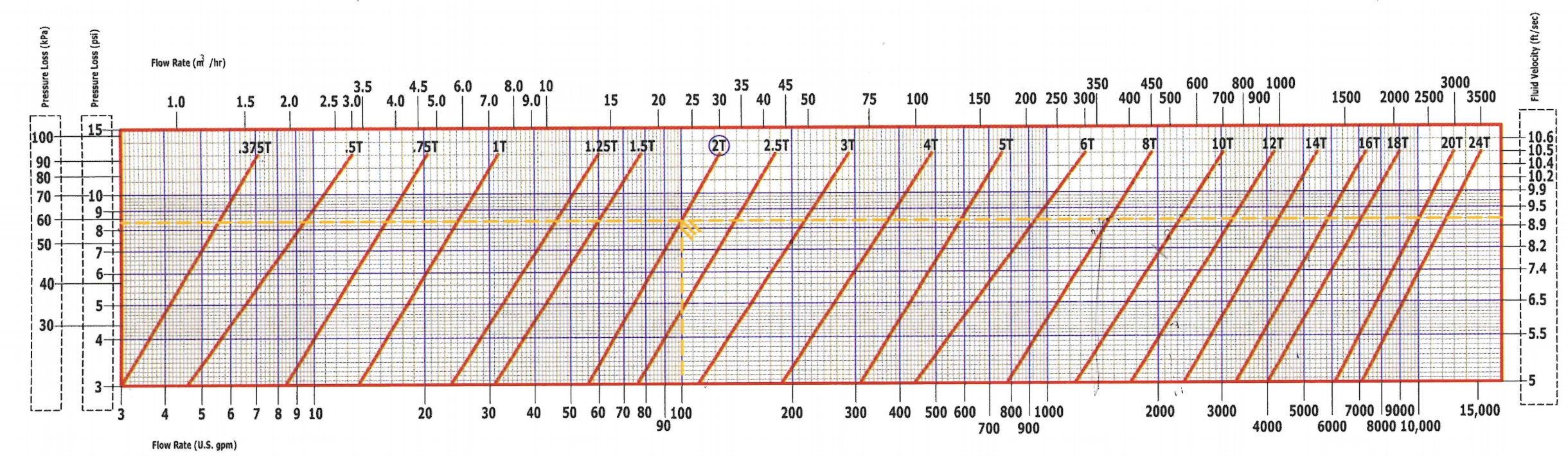
The separators require about 6 to 7 PSIG or internal velocities of around 7 FPS for the best efficiency.
What the Sediment Separator Will and Won’t Do
Separators will filter particulate, in the range shown above, if the specific gravity of the debris is over 1.7 or so. In English, if you shake a sample container of the water, anything that falls to the bottom in seconds will be filtered out. If it floats, it may not be filtered by a separator.
The omnipresent cottonwood seeds and fall fresh leaves will not be filtered. We normally suggest a bird screen in the tower basin and a strainer at the pump for these troublesome objects.
Why do I Need a Separator if I have a Strainer?
The short answer is, normally you don’t need a separator. In larger piping systems over 3”, the strainer typically has 1/8” perforations. Normally the cooling towers do not have noticeable airborne particulate. A small amount of particulate is not an issue for pumps and condensers. It all depends on the seal in the pump, the orifice sizes and tubing in the condensers, and the quantity of debris. If “normal” is not how to describe your project, look to a separator for the solution.
Previous R. L. Deppmann Monday Morning Minutes addressed seals applicable in dirty systems and strainer particulate size. I have not written about condenser tolerance to debris, so check the specific manufacturer’s recommendations.
If it looks like an issue, specify a Griswold Sediment Separator.
Where Should the Separator be Piped?
There are multiple possibilities to locate a separator in a variable flow tower/condenser water system but there are only two that we would suggest. Let’s look at four diagrams and offer the benefits and concerns of each.
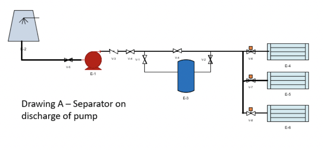
Drawing “A” has the advantage of using the pump pressure coming into it. If the pump head includes the separator pressure drop, this system can work fine in a constant flow system. In a variable flow system, this installation may have a large issue. When only one condenser is operating, the flow through the separator may drop below the minimum velocity to be effective.
I show it in a bypass so the separator may be serviced without chilled water shut down.
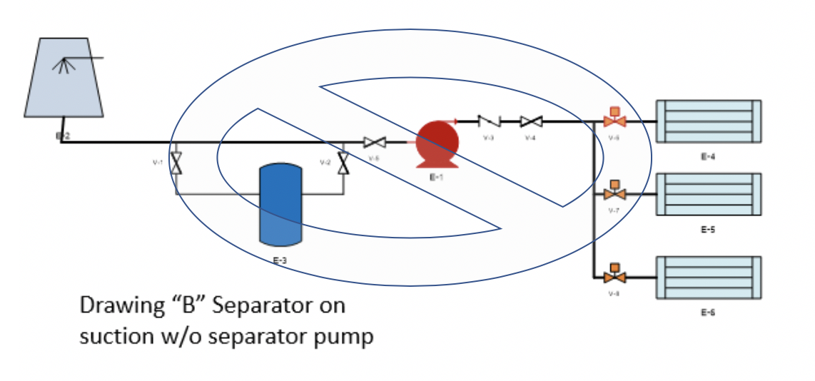
Drawing “B” is the worst thing you can do. Drawing “B” has the separator on the pump suction. The purpose was to remove the sediment before the water enters the pump, possibly affecting the pump seals.
This clearly breaks the cooling tower pumping rule: never put a high-pressure drop device on the suction of an open cooling tower. This installation also has all the variable flow and variable speed issues of Drawing “A”. We also have a concern in causing pump cavitation.
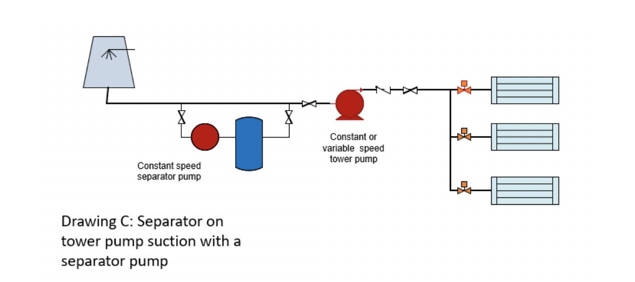
Drawing “C” is a great solution if the tower pan is above the top of the separator. The constant speed pump in front of the separator is sized to handle the proper flow and pressure drop of the separator. We have the advantage of separation of particulate at the inlet of the cooling tower pump. This works if the goal is to keep fine particles out of the condenser or free cooling heat exchanger.
Remember a few rules:
- We want the separator pump suction at the same level or below the suction pipe to the cooling tower pump.
- The tower pan is above the top of the separator. If the tower pan is lower than the separator, there are issues at startup and shut down of the pumps. It might be able to work but it would need discussion.
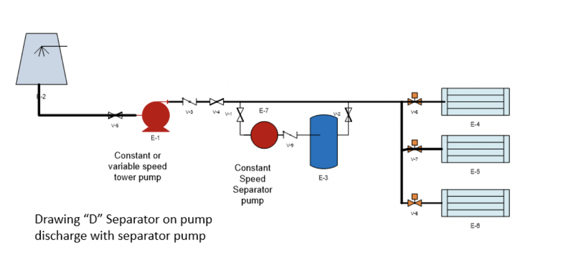
Drawing “D” is also great. It works better if we have a low cooling tower pan. It has all the advantages of drawing “C” except it does not filter the water before the pump seals. If the concern is the condenser or free cooling heat exchanger. This would be preferred.
Next week we will look at how the one pipe primary loop works in variable flow systems and look closer at the separator example. The following week we will show one more separator system sometimes called a cooling tower sweeper system.