Printer Friendly (PDF)
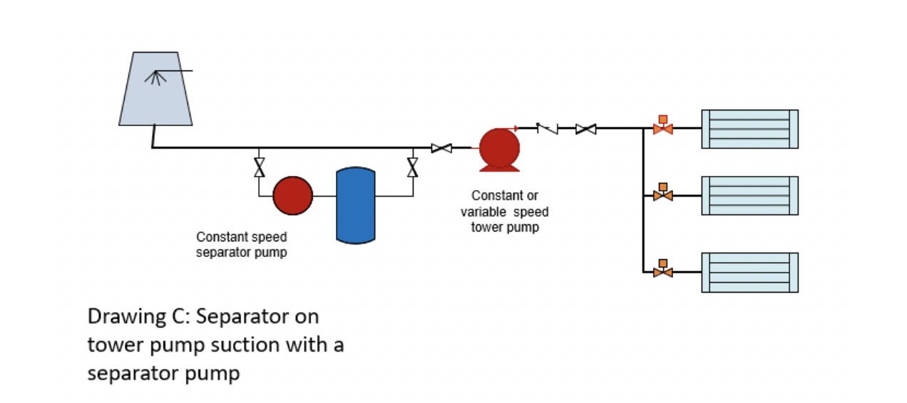 The last R. L. Deppmann Monday Morning Minutes offered suggestions for the use of a Griswold sediment separator in a variable flow tower system. The diagram shown in that article is a primary-secondary system with a variable speed primary and a constant speed secondary. Today, we’ll review the flow in the piping around this sediment separator.
Piping and Flow Rates in an Example System
Let’s look at a system with three condensers. The tonnage is 100-300-300 with one condenser operating as a standby. The flow rates using a 10°F ΔT will be 240 GPM, 720 GPM, and 960 GPM if the small tower operates with one of the larger ones.
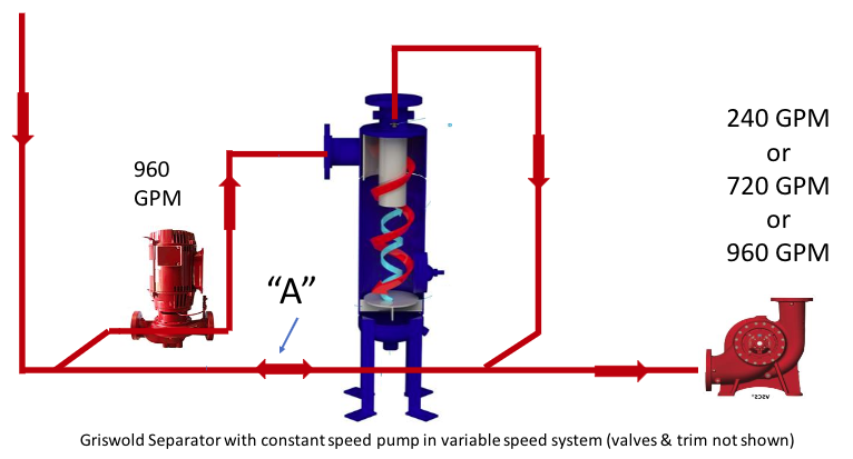
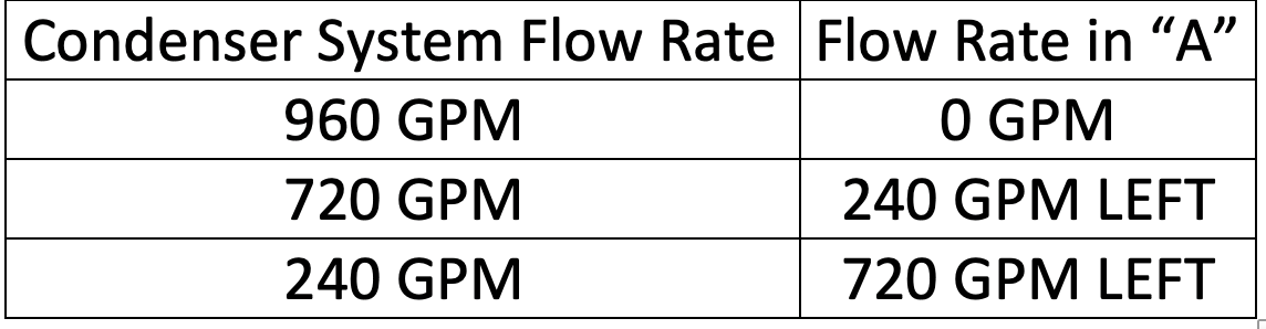
What will the flow rate be in the line marked “A” as the flow rate changes in the cooling tower pump? Let’s assume the required flow rate for the separator is 960 GPM at 9 PSIG. We will assume the pump is designed for 960 GPM at 25 feet. Let’s look at that flow rate in line “A”.
Sediment Separator Pump – Constant or Variable Speed?
We sometimes get asked about the use of a variable speed drive for the separator pump. The separator requires high-velocity flow to remove the most particulate. In this example, we would use a model 6T-FLG. The minimum flow would be about 600 GPM. At the 720 GPM flow rate, the separator could work at the lower pressure drop of around 16 feet including the piping. At this lower flow rate, the efficiency will drop down but the separator will work. The separator will not work well at the 240 GPM flow rate because of the much lower velocity through the separator
Your decision will depend on how often the system will operate at 720 GPM vs 960 GPM vs 240 GPM and how much efficiency you need. Remember, as the flow rate drops, so do the per pass percent of solids removed and the minimum size of the solids removed. The choice is energy savings vs efficiency of separation.
Variable Speed Control Head
The control head will determine the minimum flow. In this case, we have two or three different control heads. This makes it different. In this application, we want the BMS to close a set of contacts for each operation and fix the speed to maintain the flow rate required.
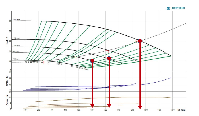
At 960 GPM the contact closure will operate the pump at 1580 RPM; at 720 GPM – 1100 RPM; and at 600* GPM – 961 RPM. * Note that at 240 GPM, the separator will not function so the minimum flow would be 600 GPM.
Next week, we will show one more separator system often referred to as a cooling tower sweeper system.