Printer Friendly (PDF)
R. L. Deppmann Company receives calls about the size and the length of the common pipe just about every week. Gil Carlson, ASHRAE fellow and Head of the B&G engineering department in the 1950s and 1960s, said, “Keep the common pipe equal to two close tees with no more than one foot of piping between them.” Today, the Monday Morning Minutes explores the primary secondary rules and what may happen if you stray from that rule.
A Key Point in Primary Secondary Systems
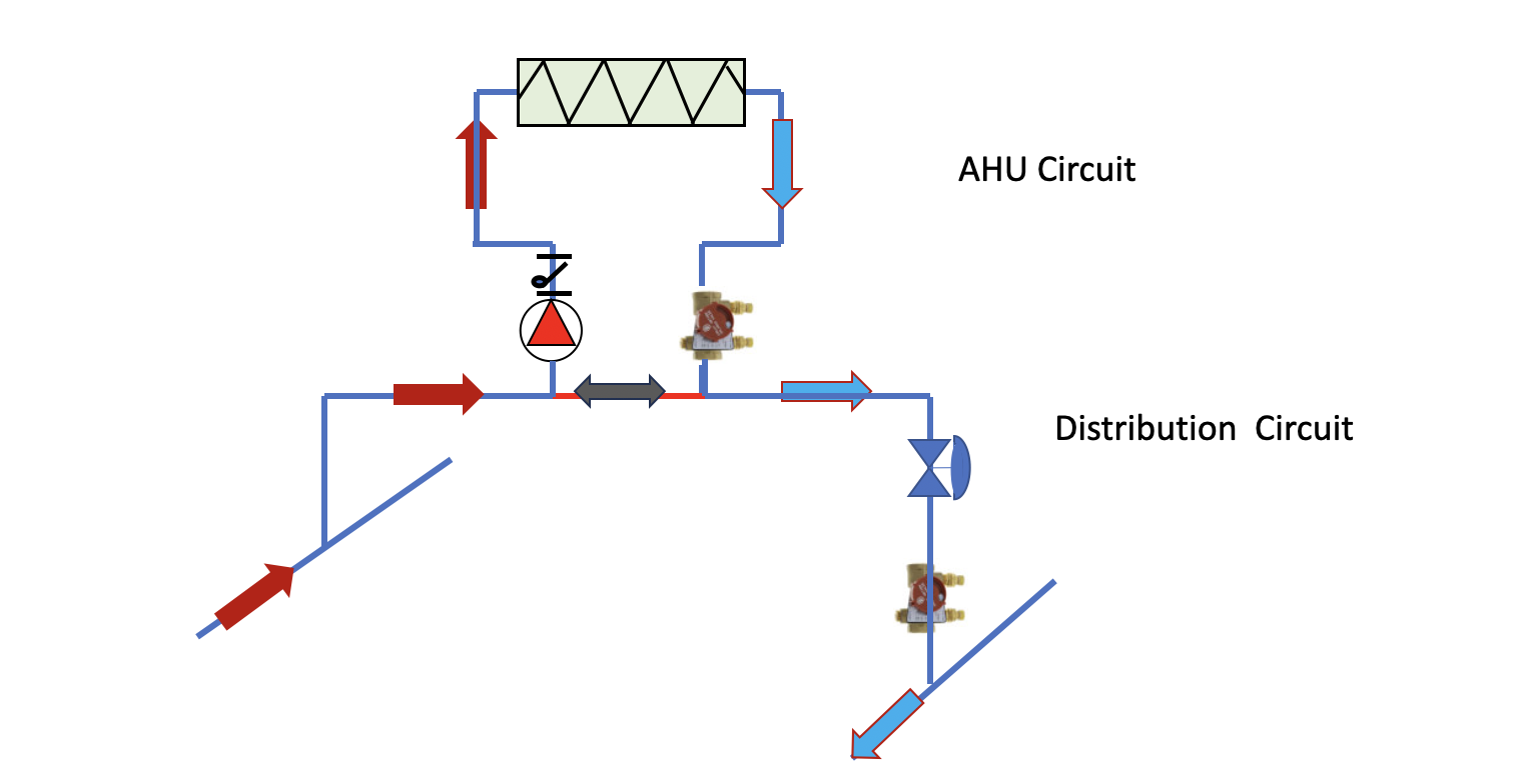
Gil Carlson, photo above from ASHRAE Pioneers of Industry Award, developed and simplified many hydronic sizing and piping procedures. One key point he often stated about primary secondary piping and balancing techniques was, “When two piping circuits are interconnected, flow in one will cause flow in the other, to a degree depending on the pressure drop in the piping common to both.” You may want to review this concept at a previous blog, Hydronic Primary-Secondary Piping – How Important are the Two Close Tees?
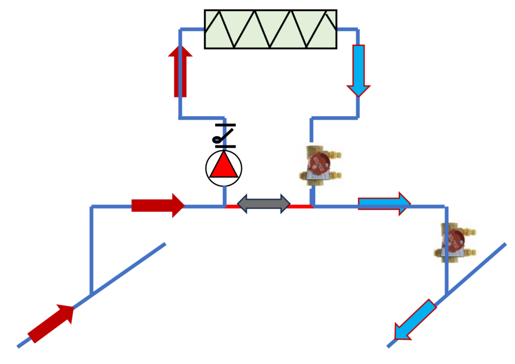
The bridge and the common pipe are shown in the Bell & Gossett technical manual, TEH-775A available through the link on our website. A representation is shown above in this article. The common pipe is suggested to be no more than two “through” tees and one foot of pipe between them. The flow passing through the tee rather than branching off provides less pressure drop. Why did B&G recommend such a specific piping detail?
Secondary System Temperature Control History
We mentioned in last Monday Morning Minutes that the zone control did not use control valves but simply cycled the pump on and off. The pressure drop in the common pipe will cause some minor flow in the zone which could overheat the space. Let’s look at a quick example of the master bedroom in the mansion identified in part 1 of this series, Primary Secondary Piping Basics: Part 1 – Terms.
Example: Assume the bedroom radiators required a flow of 3.5 GPM at a head of 6 feet and were piped with ¾” pipe. The common piping would only have 0.12 feet of pressure drop. Seems small but it could cause a ½ GPM flow rate. Based on the flow tolerance curves in Balancing HVAC Hydronic Systems Part 1: Flow Tolerance, that would end up radiating 30% of the room’s design BTUH. The room would overheat in the spring and fall. We used things called gravity checks or flow control valves to keep this from happening. You can read about that historical issue in Flo-Control Gravity Check Valve Replacement . Once the pressure drop got over 1.4 feet, the overheat would continue. That is why there was so much attention paid to keeping the piping pressure drop to a minimum.
Primary Secondary Piping with a Two-Way Control Valve
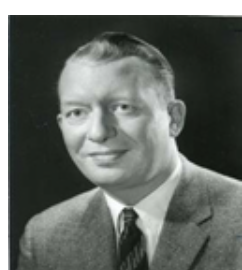
Look at the same coil shown above but let’s add a control valve. Remember, last week I said to make sure you are calling things the same as the person you are speaking with. I am going to call the coil piping and pump the AHU circuit and the bridge that is supplying the hot water will be called the distribution loop.
We put a two-way valve in the bridge of the distribution loop. The coil circuit pump can run continuously to provide some level of freeze protection. The two-way valve will modulate to maintain the temperature control of the leaving air. As the two-way valve throttles, we have mixing in the bridge and the supply temperature to the coil drops to provide the temperature control.
Does it really matter if there are two close tees and a foot of pipe in the common pipe? We have continuous flow in the AHU anyway. That does not mean we can get crazy with common pipe pressure drop but it is not as critical.
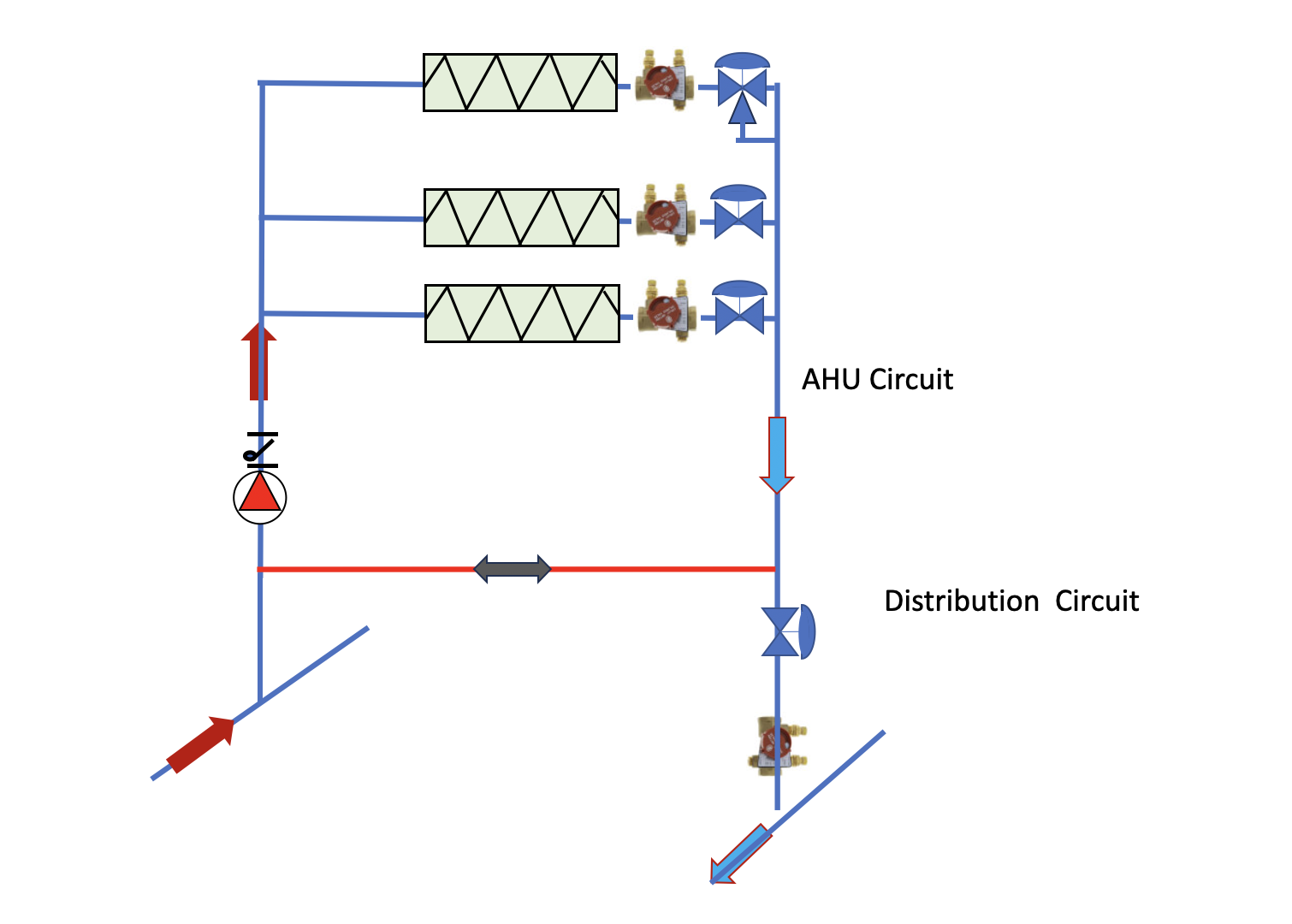
Now look at this piping. We have multiple coils in the AHU circuit. Each coil has its own temperature control valve. The AHU circuit will have variable flow, so you better use a glycol solution to prevent freezing. We also have variable flow in the distribution circuit. The last coil in the AHU circuit has a three-way valve. This protects the pump from operating at zero flow. Of course, if you use a smart pump such as the B&G Ecocirc, there is no need to have the three-way valve since the pump protects itself from minimum flow issues.
Next week we will look at a boiler system primary secondary piping example and show why you cannot get too much pressure drop in the common pipe and we will also look at what is “too much.”
Part 1: Primary Secondary Piping Basics: Part 1 – Terms