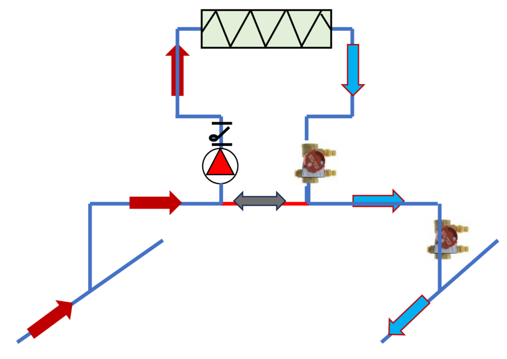
The basic design concepts of piping are important for a properly operating hydronic heating or cooling system. We have a great number of new engineers, contractors, wholesalers, and owner personnel in the industry. I thought some basics blogs occasionally would be helpful. Today, we present primary secondary terms and offer some thoughts on how confusion starts with these terms.
Primary Secondary Piping Terms
This may be too slow a start, but it is important that all the readers use the same terms. Look at the traditional “textbook” representation shown above. This shows some distribution piping often called the primary loop and a terminal unit coil piped as a secondary loop. I did not show the shut-off valves, gauges, and thermometers to simplify the sketch.
Here are some basic terms.
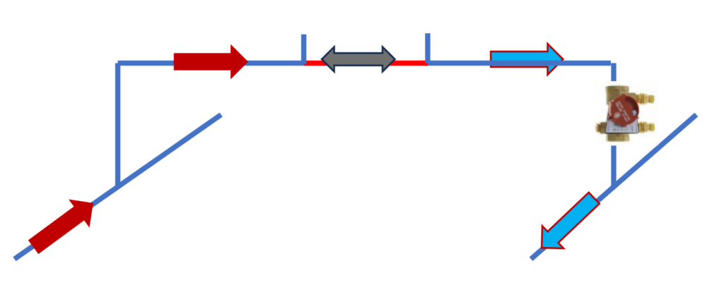
This could be called the “Primary Loop.” It provides hot or cold water to the secondary loop. In this case, I show a “bridge” or the piping from the supply pipe back to the return pipe. Since the bridge could have any amount of flow rate in it, I include a combination balance valve and flow meter on the return of the bridge. The example above uses a Bell & Gossett Circuit Setter. Notice the orange-colored pipe on the bridge. It is simply a piece of horizontal piping, but it is called the common pipe. It includes the two through tees and the small piece of pipe shown in orange.
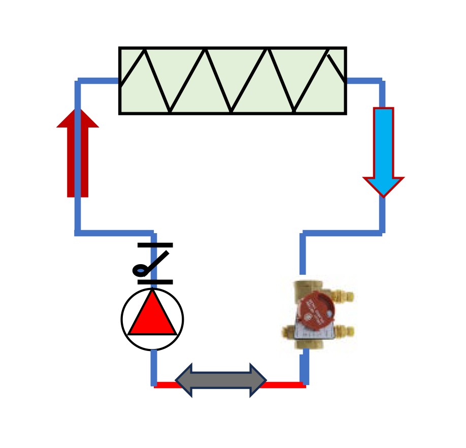 This could be called the “Secondary Loop”. It receives hot or cold water from the primary loop. In this case, it includes the pump, the coil, the interconnecting pipe, and the same common pipe shown in the primary loop.
Two things make this a primary secondary system:
- Each system has a separate pump that pumps its circuit.
- There is some piping that is common to both systems. That “orange” piece of pipe is pumped from the pump on the distribution system (not shown). It is also pumped from the secondary pump.
The pressure drop in the common pipe is included in the pump head calculations of both pumps. This fact is important to remember when we mention its size and pressure drop in part two of the series.
Secondary System Temperature Control
Notice there is no control valve shown on the coil in the secondary system. These systems were originally explained in the 1940s by Gil Carlson of Bell & Gossett. At that time most hydronic systems were installed in houses. Motorized control valves were huge, expensive, and noisy. That part of our industry was just blossoming. The secondary loop could be controlled by simply turning on the secondary pump when heat was needed and turning it off when the thermostat was satisfied. You may think that is archaic but that is how most residential furnace systems work today. On and off control. Let’s look at an example.
 Think of a large two-story mansion in the first half of the 20th century in glamorous Grosse Pointe Michigan. Mr. Auto Exec hired an architect to design what he called a house. He wanted to heat the downstairs living area spaces, the kitchen, the master bedroom, and the other six upstairs bedrooms all independently. What a concept!
The engineer would design a primary secondary system and cycle a pump for control of each zone. We will use this example and introduce one more term often used.
Primary Secondary Tertiary Systems
There is really no limit to the number of pumped systems you can have attached to other systems. Let’s look at the simple layout of the example system above.
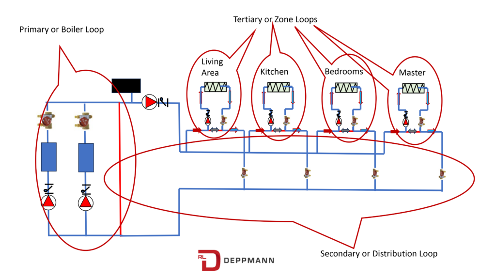
Here is a representation of the “house” described above. The primary loop is where the boilers are shown. The secondary loop is the distribution system. The individual zones are each called a “tertiary” or “zone” or “coil” loop. Now watch out for terms. In the beginning of this blog, I showed the distribution as the primary loop. Never assume the person you are speaking with is thinking of the same picture. When describing a system, always add a few words.
This example does not have control valves. The pumps all turn on and off for control. There would be an issue with gravity circulation. Even if the pumps were off, the hotter water may rise and overheat the master bedroom. There is no control valve to stop flow. We used things called gravity checks or flow control valves to keep this from happening. You can read about that historical issue in Flo-Control Gravity Check Valve Replacement.
Next week we will talk about that common pipe a bit more and why proper sizing is important.

