Printer Friendly (PDF)
 The engineer is aware of the importance of minimum flow to the pumps in hydronic systems. The R. L. Deppmann Monday Morning Minutes Part 1 showed how to calculate the minimum flow required. Part 2 showed examples of creating the minimum flow out at the ends of the system loops. Today, we address the issue of minimum flow in primary variable systems.
The Issue of Minimum Flow in Primary Variable Systems
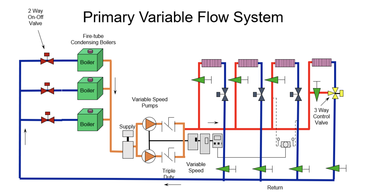
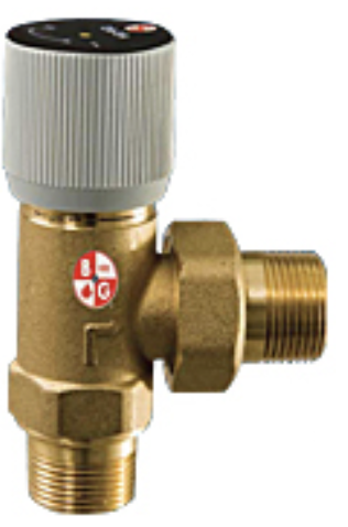
ASHRAE 90.1 energy standards require the use of some means to stop the flow in a chiller or boiler which is not operating. The representation above shows two-way control valves on each boiler. As boilers shut down, the valves close. When all the valves are closed, it will not matter if we have bypasses or three-way valves in the system, the flow will be “zero.”
Another challenge are the projects where the engineer is upgrading the mechanical room but not doing anything out in the system. These cases may require a minimum flow solution in the mechanical room. The minimum flow required may be due to pumps or due to the heat/cool source. Here are a few options to achieve the minimum flow rate of the pumps.
The Constant Flow Bypass
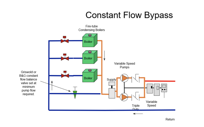
Probably the least expensive installation cost but most expensive operating cost would be a constant flow bypass. This is nothing more than the bypass with an automatic balance valve as described in Part 1 of this series, “Minimum Flow in Variable Speed Pumps for Building Hydronic HVAC Systems.” This would not be my first choice, but it is a choice. The engineer would design the system pump with a system design flow rate plus extra for the minimum flow.
The Bypass Control Valve
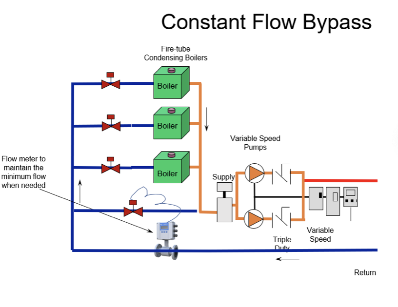
The bypass shown could have a control valve. This control valve could be modulating. The signal from the building management system (BMS) would vary based on a Badger flow meter in the main. The signal would keep the valve closed if the flow is greater than the minimum flow required. The signal would modulate the valve open to maintain the minimum flow. Note that it is important to choose a flow meter that provides accurate measurement in low velocities. This may be a place for an inline magnetic meter such as the Badger M2000. Another non-intrusive option could be the Badger TFX-5000 ultrasonic flow meter. Watch for minimum velocities when using mechanical impeller or insert magnetic meters. The two Badger meters mentioned will not have the velocity issues.
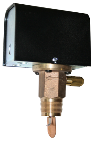
McDonnell miller fs-7-4 flow switches
One last option would be to use a 2-way on-off bypass valve with a McDonnell-Miller FS7-4 flow switch in the main. The paddle could be fine tuned to adjust the minimum flow rate and dead band. In this application, the valve would remain off until the flow switch minimum flow was met. Then the valve would be full open. I would suggest a Griswold or B&G automatic flow balance valve in the bypass line for this application.
Pressure Differential Bypass Valve – Caution
DB-3/4 – Differential Bypass Valve – Xylem Applied Water Systems – United States (bellgossett.com)
Another bypass line option is the mechanical differential bypass valve. This is a mechanical valve with an adjustable pressure differential. It is like the back pressure relief valves used in cold water distribution systems. These valves open when there is a rise in pressure differential.
The back pressure relief valve attempts to maintain the flow rate as things close downstream. These are used in constant speed applications. As the flow drops and the pump head rises, the relief valve opens to maintain the design head while bypassing the flow not being used in the system. These are fixed pressure devices and will not work in variable speed systems.
The less expensive pressure differential bypass valves are also meant to be used in constant speed applications. As the control valves close and the pump head rises, the valve opens. If these are used in a commercial application and set at the control head, they will always be open. No different than the constant bypass valve described above.
Proper Boiler Sequencing with 2-Way Valves
What about the systems where the minimum flow was designed into the distribution system? How do we employ the 2-way on-off boiler valves and still use the existing minimum flow design?
The boiler on-off control valves may seem simple to control. There are several important things the control system must accomplish. Here are just two examples. Does the control system keep the control valve open long enough to dissipate the excess heat? Does the system understand which boiler will start on a call for heat and keep that valve open and ready? This second point will allow the minimum flow system bypasses to operate correctly.
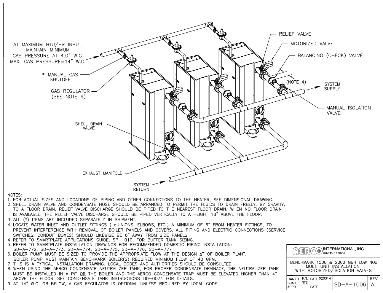
The engineer should consider employing the boiler manufacturer’s control. An example is the Aerco BST boiler sequencing technology available with the Aerco Benchmark and Platinum boilers. This built-in control will operate multiple boilers at lower firing levels, properly stage the boilers, and operate the 2-way control valves properly.
The engineer has many options to achieve minimum flow rates in hydronic systems. We hope this short series has helped define some of the options available.
Check out the rest of the series!
Part 1 : Minimum Flow in Variable Speed Pumps for Building Hydronic HVAC Systems (Part 1)
Part 2 : Minimum Flow in Variable Speed Pumps for Building Hydronic HVAC Systems (Part 2)