The 2015 Michigan Energy Code is changing with an expected effective date of September 20, 2017. The long expected changes to the code were filed with the Secretary of State on May 23, 2017 with an effective date 120 days after filing. This week the R.L. Deppmann Monday Morning Minutes looks at a few highlights of the new code.
The new code is available through the LARA website which links to ICC.
The code follows ANSI/ASHRAE/IES Standard 90.1-2013 with some modification. The prior Michigan Energy Code aligned around ASHRAE 90.1-2007 standards. There are many changes from the 2007 ASHRAE standard to the 2010 Standard, and even more from 2010 to the 2013 standard which the new code is based on.
R.L. Deppmann seminar series have captured these changes and alerted engineers and contractors to the design changes required in hydronic systems. Here is a quick summary of some of the key changes.
Water Side Economizers and the 2015 Michigan Energy Code 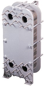
6.4.1.4 Plate type heat exchangers such as those used in water side economizers or free cooling must meet the requirements of the AHRI 400 test procedures. This is an important change that must be incorporated into your selections and specifications. Bell & Gossett GPX plate exchangers meet this requirement.
6.5.1.3 Although this is not a change, I should remind you that the maximum pressure drop of water side economizers was limited to 15 feet in prior standards. We still see some schedules defaulting to the old “rule of thumb” of 10 PSIG or 23 feet.
Boilers and the 2015 Michigan Energy Code
R.L. Deppmann Company is a leading manufacturer’s representative in boilers and water heaters. The ASHRAE 90.1-2013 Standard contains a couple of key changes affecting these systems. Our experience is that most engineers have incorporated these change into today’s design. 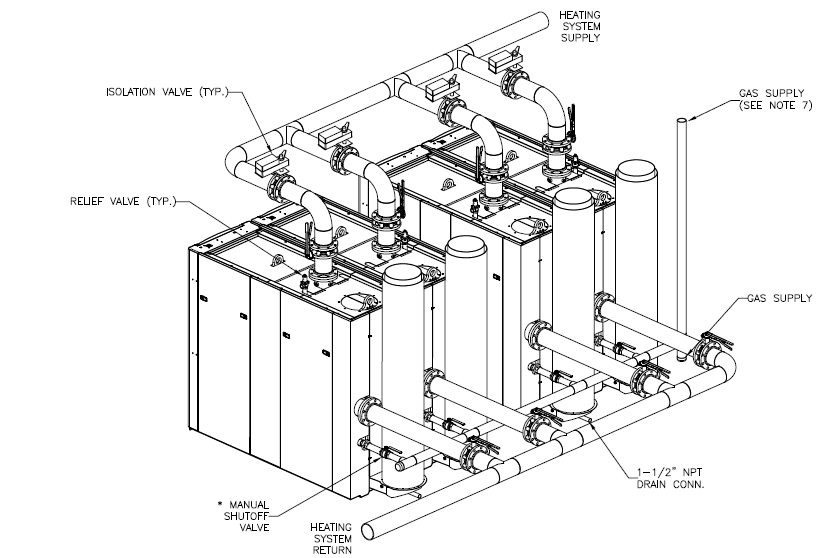
In systems where the plant has more than one boiler or chiller, section 6.5.4.2 of the standard requires that we stop the flow through the boilers and chillers that are not operating. Obviously this can be accomplished through dedicated pumps, but in systems where the pumps are on a common header, the use of isolation valves is required.
Today most boilers scheduled are high efficiency and have great turndown but the standard (6.5.4.1) indicates the turndown must be a minimum of 3:1, 4:1 or 5:1 based on size.
HVAC Pumps and the 2015 Michigan Energy Code
You must calculate the pump head including the pressure drop through the worst terminal unit and the piping losses to it. (6.4.2.2) Most engineers do this already but this eliminates the “rules of thumb” or estimating of pump head.
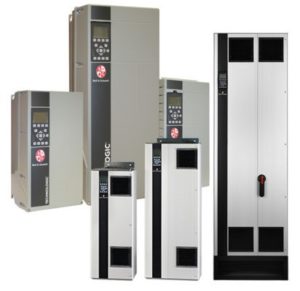 The 2007 version of ASHRAE 90.1 standards required hydronic systems be designed for variable flow with a few exceptions. It also had a requirement for pumps with heads over 100’ and horsepower of 50 or greater to be able to drop the energy used to 30% of the wattage at 50% of the flow. This limitation was changed (6.5.4.2) to any system pump over 5 HP in chilled water systems with a couple of exceptions for smaller systems. Deppmann offers many variable speed pumping options to meet this portion of the code.
The control of the pumps to reduce wattage to 30% at 50% flow should be controlled by differential pressure (DP) or by desired flow. (6.5.4.2 ) Bell & Gossett offers both sensor control and sensor-less control. Remember that you can use either type of control with any pump and the choice of base mounted or inline pumps and the choice of pump control are separate decisions. There are some manufacturers that only market one type of pump with sensor-less control.
Most systems today are already using the DP set point for control. The DP set point shall be measured at the controlling heat exchanger (terminal unit) and be set to no more than 110% of that needed. This means the 10 PSIG “rule of thumb” must now be calculated. R.L. Deppmann has many seminars explaining how to do this properly. All of our sales engineers understand this and can help you with the calculation. On larger systems with a total of 75 HP or more, if DP control is used, DDC reset of the set point downward until one valve is nearly wide open. (There are exceptions listed.)
HVAC Hydronic Pipe Sizing and the 2015 Michigan Energy Code
Engineers and contractors all use various methods for pipe sizing. The Bell & Gossett system syzer® wheel has served us well for decades. 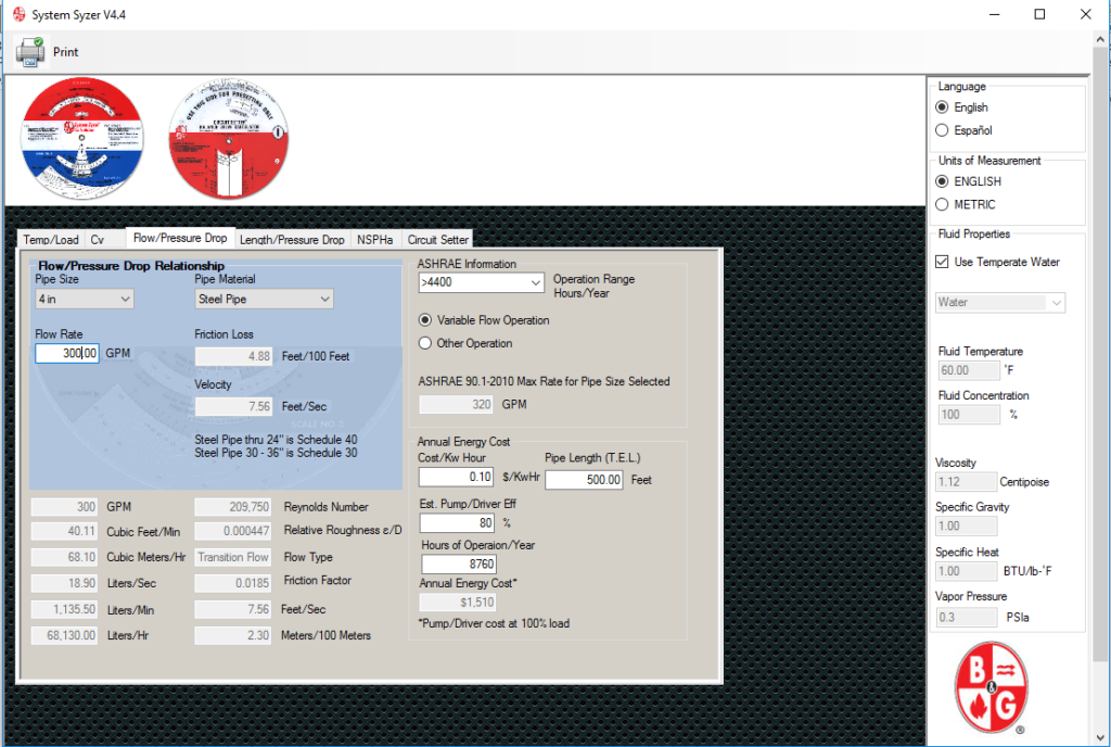
The standard has a new pipe sizing chart that varies the maximum allowable flow rate through a hydronic system based on hours of operation. (6.5.4.6) The standard is clear that the numbers published are the maximum and there is no issue if your office standards of flow in pipe is less than that published. Bell & Gossett has published an electronic system syzer® (the wheel) for your computer or mobile device which makes it easy to select pipe size based on this chart. Visit our website to download these and other tools.
The Devil’s in the Details
This term is not one I use but I still hear once in awhile. In this case it is true. I’ve given you a brief outline to help you understand some of changes, but the words used are not the exact words in the 2015 Michigan Energy Code. In addition there are exceptions based on use and size of the systems. Read and understand the code before submitting your design for approval. September 20th has come and gone so now is the time.
Next week the R.L. Deppmann Monday Morning Minutes continues to the subject of Gauges and Thermometers in HVAC and Plumbing Systems.

