Printer Friendly (PDF)
Primary-Secondary TEH Manual
Primary Secondary (P-S) hydronic piping is a common piping scheme in today’s hydronic heating and cooling systems. This short series of blogs will provide examples of piping schemes which will support the reduction of hot water return temperatures to enhance the value of condensing boilers. The first article will just review the rules of the road in P-S piping.
Bell & Gossett (B&G) makes their Primary-Secondary Pumping Application Manual TEH-775A manual available online. Visit our R. L. Deppmann design tools section of the website for the link. This will offer a lot more detail then I can cover in the few minutes of reading I offer here.
Primary-secondary is often used for boilers and freeze protection loops in heating systems. This design is also used for decoupling constant flow chillers from variable speed supply systems. There are basic rules for these systems. It never hurts to do a quick review of a basic subject.
Primary-Secondary Basics – Decoupling the Systems
B&G introduced the primary-secondary design for hydronic pumping in the 1940s. At that time, many secondary circuits cycled the constant speed pump on and off to achieve temperature control. It was important that the flow stopped when the pump was off. They often mentioned 2 close tees with less than 1 foot of pipe between them. Let’s look at this rule.
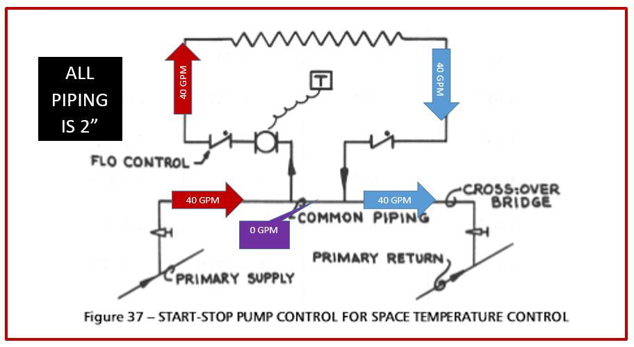
Figure 37 from the Xylem Bell & Gossett Primary Secondary Pumping Manual TEH-775A
When the secondary pump is shut down, the flow rate in the primary pipe flows through the common pipe and back to the return. The piping common to both the secondary and primary loops are the two tees and the common piping shown above.
Rule “1” tells us to keep that common pressure drop very low. The reason being if there is nothing to stop it, the pressure drop in that pipe will cause a flow in the secondary circuit, even if the secondary pump is off. Let’s look at the system shown above as an example.
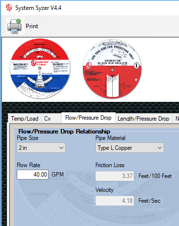
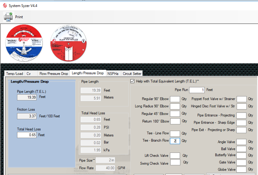
Assume the secondary pump is designed for 40 GPM at 15 feet. The assumption is that when the secondary pump shuts down, the primary pump will not allow flow in the secondary circuit. How much pressure drop will we have in the two branch tees and 1 foot of pipe? The B&G System Syzer shows us that 2” pipe at 40 GPM is 3.37 feet of pressure drop per 100 feet. The flow/pressure drop tab shows a total of 0.65 feet through the 2 tees and 1 foot of pipe.
How much flow will this cause in the secondary? We use the second pump affinity law to find out.
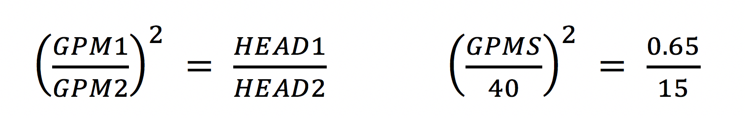
Even these two branch tees with a foot of pipe will cause 8.3 GPM of flow rate. This will overheat the space in the spring and fall. This is where the flow control valves come into play.
B&G Flow Control Valves Stop Unwanted Circulation
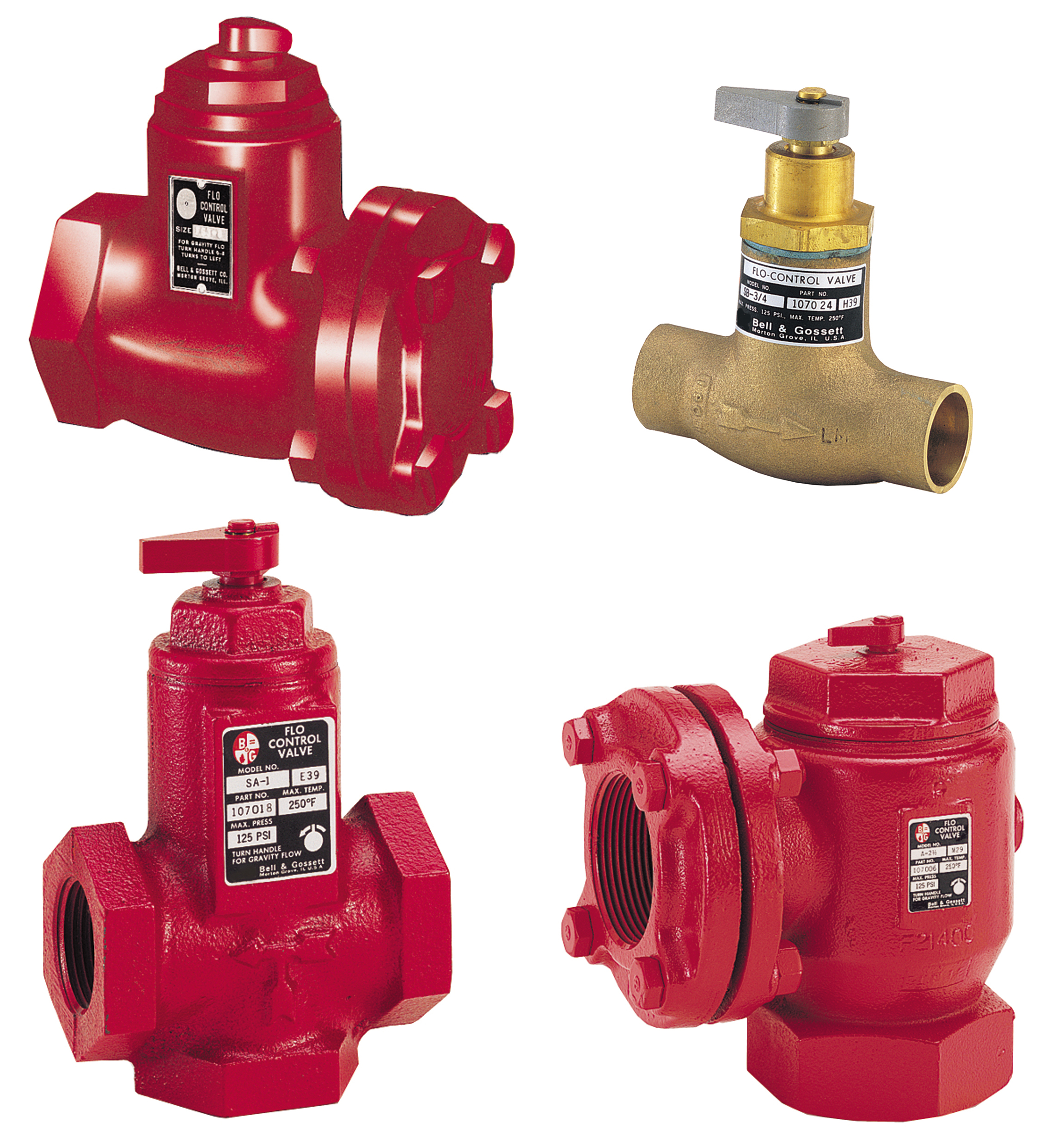 In order to stop that 0.65 feet of common head from causing unwanted secondary flow, we add a device to the system. In the sketch above we show a “Flo Control Valve”. This is a weighted check valve to prevent the flow mentioned above to occur. It takes ½ lb. to lift the weight. This can also be accomplished through the use of Metraflex spring-loaded check valves.
The valve on the supply is used to stop the unwanted flow and also gravity circulation in the heating system. The one on the return is used to stop gravity circulation. The gravity circulation can also be stopped with piping methods which are outlined in the B&G manual.
Next week the R. L. Deppmann Monday Morning Minutes will use the “Law of the Tee” primary-secondary rule to explain how to set up hydronic heating systems for a lower return temperature.
