Printer Friendly (PDF)
Primary-Secondary TEH Manual
Primary-Secondary hydronic piping is a common piping scheme in today’s hydronic heating and cooling systems. This article will show you how to use this common piping technique to vary the secondary supply temperature using balance and “The Law of the Tee.” We will also show you how to solve issues of staged loads using the same techniques.
Primary Secondary Basics – “The Law of the Tee”
Primary-secondary design is often used for boilers and freeze protection loops in heating systems. It is also used for de-coupling constant flow chillers from variable speed supply systems. In the last article, we described the close piping requirement to prevent unwanted circulation. Now we look at “The Law of the Tee.”
“The Law of the Tee” sounds more profound than it is. Basically, it says the flow into the tees has to match the flow out of the tees. It also says that the BTUH in the secondary design must match the BTUH provided by the primary.
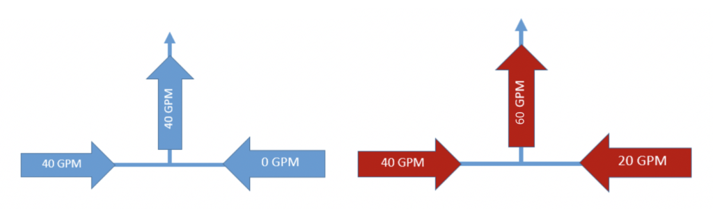 Flow into the tee must equal flow out of the tee
Similarly, we must have a heat transfer balance between the primary and secondary systems. When there is a lower supply temperature in the secondary circuit, the primary flow rate will be reduced.
Primary-Secondary Example: Radiant Heating System
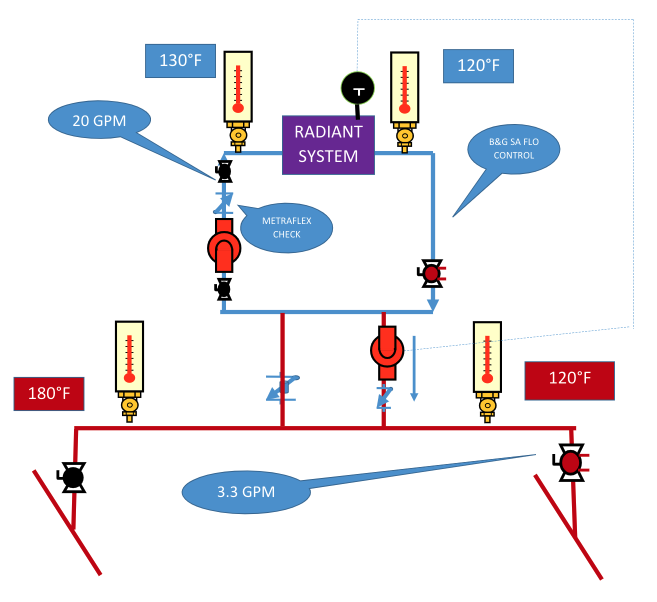
Let’s assume the design is for a radiant system with a load of 100,000 BTUH requiring a supply of 130°F and 120°F return. The flow rate is 20 GPM. If the primary supply water is at 180°F, how much do I need? The system looks like this:
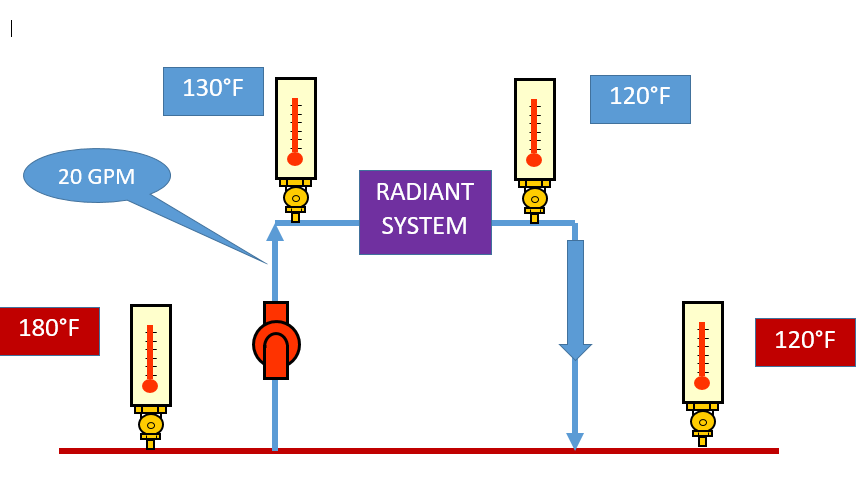
Secondary System = 100,000 BTUH = 20 GPM X (130-120) X 500
Primary System 100,000 BTUH =? GPM X (180-120) X 500
Primary? GPM = 3.33
The piping to the bridge from the primary system can be sized for 3.4 GPM. The two tees and the common piping should be 2” in our example. Remember, the two tees and the common pipe has to handle 20 GPM. The primary pipe may be ¾”.
Two-way Control Valve and Trim for Primary-Secondary
In a radiant system, we normally have a constant flow secondary. The control valve is located in the primary bridge piping. This will give you great control! The secondary radiant system only has a 10°F delta T. The primary bridge has a 60°F ∆T which is a much larger range to control within. It does not hurt that the control valve is smaller/less cost and the pressure drop of the control valve is in the primary bridge where we want the pressure drop. If the bridge is near the mechanical room we would be adding pressure drop through the balance valve anyway. The control valve would not add to the primary pump design head. The secondary pump head, typically, remains very small in this application.
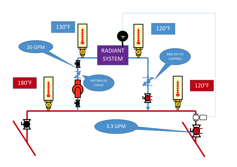
The trim includes the spring-loaded Metraflex check valve and the Bell & Gossett “SA” weighted check flow control valve. These items avoid gravity flow which was discussed in our blog, Hydronic System Primary Secondary Rules- Decoupling Systems.
Injection Pumping Control in Primary-Secondary Pumping
On certain systems, you may want to use an injection pumping system for control. This uses a small variable speed pump instead of a control valve. Let’s look at this system.
This arrangement could be called the “friend of the pump supplier” system, (smiling). The control valve is replaced by a very small pump. There are good reasons, besides getting to sell you another pump, to employ this control.
- First, this allows for constant flow primary and secondary systems if that situation is required.
- The second is energy conservation. I have eliminated the 5 PSIG pressure drop of the control valve from the primary loop. If this was a determining loop in the primary pump head, you will save energy.
- Third, if you are looking for a minimum flow loop in the primary, this will provide some of that GPM without using a bypass valve and the controls associated with it.
Finally, this pump is really small! The pump can be a small constant speed 9-watt inline pump like our Bell & Gossett model “NRF”. In this case, the controls would simply cycle the pump on and off for temperature control. It could also be one of the Bell & Gossett inline variable speed circulators and vary the speed to control the temperature.
Next week the R. L. Deppmann Monday Morning Minutes will look at an Air Handling Units with lower return temperatures.