Printer Friendly (PDF)
 Hydronic heating system buffer tanks are used to add water volume to the system to help avoid excessive cycling of the boiler. How do you size a buffer tank and when do you need one?
The Formula Used to Identify Required System Volume
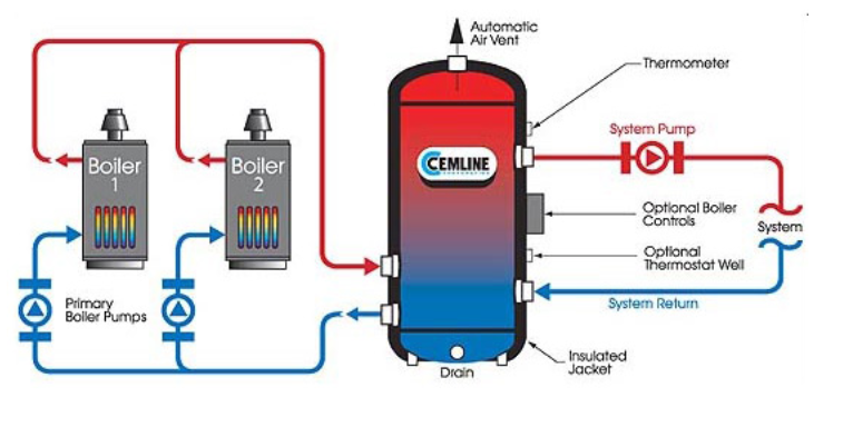
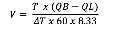
In part 1 of this series, we looked at the location of a hydronic heating system buffer tank. The system volume is important. We want a boiler to operate for a minimum amount of time when at low fire. While it is firing, the boiler is putting some amount of BTUs into the water. As long as the water has the capacity to accept the BTUs, the boiler will keep firing. Here is the formula used for systems using water:
This formula is available from many sources. We took this from the Cemline System Efficiency Buffer Tank sizing program since we represent their products. Many other tank and boiler manufacturers have similar sizing methods.
V is the combined volume of the buffer tank and the system volume in gallons.
V minus the system volume is the tank volume required. A special note if this is a combination heating and domestic hot water heat exchanger application. In the summer, the only system volume you will have is the primary boiler piping loop to the heat exchanger.
T is the minimum suggested boiler firing time.
This time is meant to keep the boiler from cycling on and off too frequently and is determined by the boiler manufacturer. A “rule of thumb” is no more than 6 starts per hour so 60/6 = 10 minutes.
QB is the BTUH boiler output at the minimum fire of the boiler.
If a boiler is rated 6,000,000 BTUH output with a 5:1 turndown, QB is 6,000,000/5 = 1,200,000 BTUH
QL is the minimum required load of the system.
This is the load expected when the boiler is barely needed. Many times, the tank manufacturers just say to use “0”. We deal with commercial systems every day. What do I recommend? Assume a normal heating system with no process or dump load. I recommend 3% of the design BTUH of the system with no safety factors. Example: 6,000,000 BTUH with no safety factor is the design load.
QL is 3% of 6,000,000 or 180,000 BTUH.
I could spend an entire Monday Morning Minute explaining where I came up with that.
ΔT is the temperature drop within the tank.
This is a place where people differ. Some manufacturers say to use the design temperature difference of the system. Cemline, and many others, say to use the temperature difference in the tank. I say to use the difference between the boiler on setting and the boiler off setting or the dead band.
Example: A boiler has a design set point of 180⁰F. We would normally set the boiler to shut down at 185⁰F. On a lower turndown ratio boiler, we would set the starting point at 10⁰F below the set point or 180-10 or 170⁰F. This would give a ΔT of 185-170= 15 ⁰F.
If greater control is needed or the turndown is larger, the boiler dead band from set point to boiler start may be 5⁰F or 175⁰F. In the example, ΔT would become 185-175 = 10⁰F
60 x 8.33 are the constants required to covert hours to minutes and pounds to gallons. Please note: if you are using glycols in the system, the 8.33 is replaced with (8.33 x specific heat x specific gravity)
Cemline Standard 4 Pipe Heating Buffer Tanks
Cemline will build tanks to match the needs and special space requirements of the customer. They do offer some standard cataloged models of heating system buffer tanks which they call the “System Efficiency Buffer” tank or SEB.
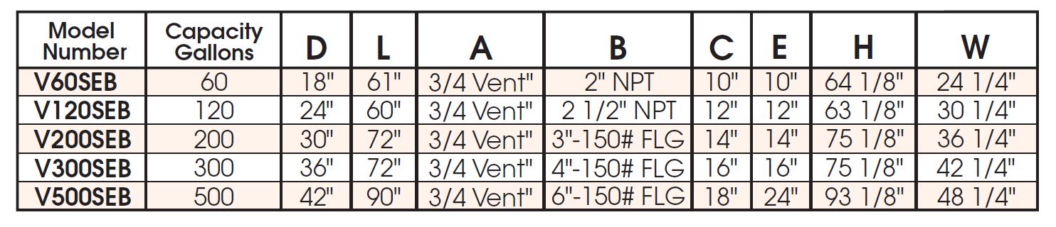
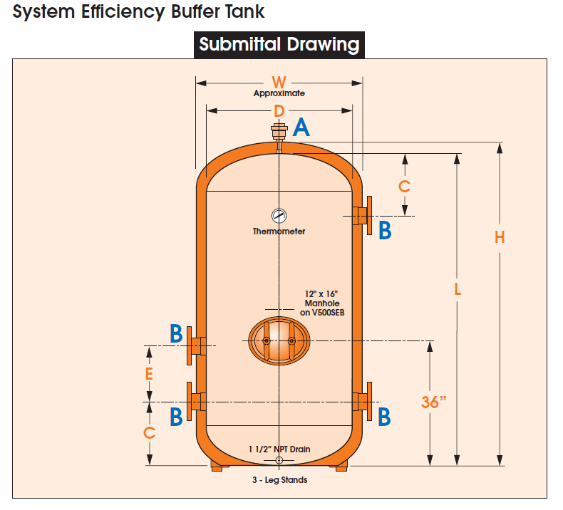
These tanks can be custom designed. The four port design is meant for primary-secondary applications. It will also be used as the bridge common pipe or hydraulic separator. Two port designs are available with different model numbers for primary variable applications. The models shown above are all 125 PSIG ASME. There is a vent connection and vent included. A removable insulation blanket is available. Call R. L. Deppmann to discuss exact requirements.
It is important that the tanks be vertical. Stratification is a critical part of the correct operation of the tank.
Examples to Determine the Required System Volume
Example 1: The volume used in the expansion tank calculation with no safety factor is 1000 gallons. I have a load of 6,000,000 BTUH in my primary secondary system and I have one operating boiler with a 5:1 turndown ratio. If I use given rules of thumb, what is the required system volume and will I need a tank?
I will use 10 minutes as T and 15 as ΔT.
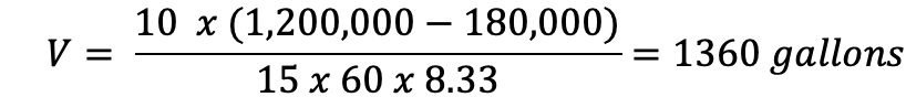
1360 gallons minus the system volume of 1000 gallons leave the required tank size at 360 gallons minimum. Use a Cemline model V500SEB.
Example 2: The volume used in the expansion tank calculation with no safety factor is 1000 gallons. I have a load of 6,000,000 BTUH in my primary secondary system. I will use (2) operating boilers at 3,000,000 BTUH each. Each boiler has a 10:1 turndown ratio. If I use given rules of thumb, what is the required system volume and will I need a tank?
I will use 10 minutes as T and 15 as ΔT. The minimum fire of a single boiler is 3,000,000/10 = 300,000 BTUH.
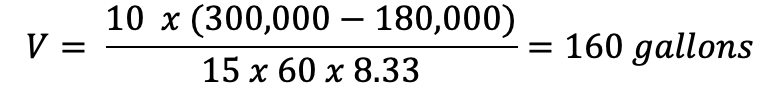
The system volume of 1000 gallons is plenty and no buffer tank is required. This system will cycle very little. In fact, we would set a tighter control band on this boiler. If the set point were 180 ⁰F, we would set the boiler temperature at 175⁰F.
Example 3: The volume used in the expansion tank calculation with no safety factor is 600 gallons. I have a load of 10,000,000 BTUH in my primary variable system. I will use (2) operating boilers at 5,000,000 BTUH each. Each boiler has a 8:1 turndown ratio. The owner has a lab process that requires tighter temperature control. If I use a cycle time of 10 minutes and a ΔT of 8⁰F. What is the required system volume and will I need a tank?
The minimum fire of a single boiler is 5,000,000/8 = 625,000 BTUH.
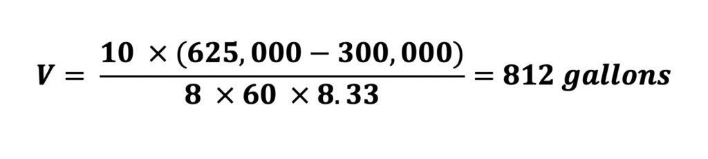
The system volume of 600 gallons is too low. We could add a custom 2 port buffer tank on the return pipe. Another option is to change the boiler to a Aerco Benchmark or Platinum 4000 with a 15:1 turndown ratio and no buffer tank would be required.
Design Considerations to Avoid Cycling
You may be a fan of primary-secondary or primary variable hydronic systems. Regardless of the system, there are some simple design thoughts to assist in reducing energy and increasing product life.
- The higher the turndown the better.
- Use multiple boilers in parallel to reduce the minimum single boiler firing rate.
- Work with your boiler representative and Cemline representative to remove any doubts about product need.
Catch up on the Hydronic Heating Buffer Tanks series below:
Part 1: Hydronic Heating Buffer Tanks – Location
Part 3: Hydronic Heating Buffer Tanks – Variable Primary