Printer Friendly (PDF)
 We know that cycling a hydronic condensing boiler on and off too often will waste energy. There are other problems caused by a boiler cycling more than the manufacturer recommends. The owner may experience more maintenance and repair costs, nuisance shutdowns, and reduced boiler life. Today, we examine the buffer tank solution.
Some Contributors to Excessive Cycling of Hydronic Condensing Boilers
There are three key system issues that contribute to excessive cycling of a hydronic condensing boiler plant.
- Low Turndown Ratio compared with the minimum load: Many water tube boilers have turndown ratios of 5 to 1. Fire-tube boilers have greater turndown ratios up to 15:1 or more. Once the boiler is at its lowest firing rate and the system load is low, the boiler will cycle on and off.
- Example 1: 6,000,000 BTUH boiler with a 5:1 turndown has its lowest firing rate of 1,200,000 BTUH.
- Example 2: Two 3,000,000 BTUH boilers in parallel each with a 15:1 turndown for a total plant capacity of 6,000,000 BTUH. The lowest firing rate will be 200,000 BTUH.
- Low System Volume: When the boiler is at its lowest fire rate and the system load is less BTUH, the gallons of water or volume of the system is important. The BTUs added to the system, but not used, will heat the water in the pipe. The “hope” is a large enough system volume to allow the correct boiler run time while absorbing BTUs. More about this in part 2.
- Example 1: Assume the 6,000,000, 5:1 boiler above should run for 10 minutes. In 10 minutes at low fire the boiler will input 200,000 BTUs into the water. (10 X 1,200,000/60) This assumes there is enough water volume to accept it.
- Low-temperature sensor dead-band: There is a temperature setting above the set point when the boiler will turn off. There is a setting below the setpoint when the boiler turns on. The tighter these are, the more water volume is needed to avoid short cycling. There may also be nuisance high limit safety issues.
- Example 1: The boiler is set to maintain 180⁰F. The boiler controls are set to shut the boiler down at 185⁰F and turn the boiler on at 175⁰F.
Heating System Buffer Tank Location: Primary-Secondary Systems
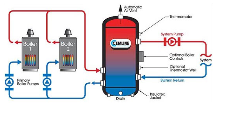
It will be easier to understand the sizing of the tank if we understand the location of the tank in the hydronic condensing boiler system. The buffer tank location in a primary-secondary application will serve three purposes.
- The prime purpose: Add volume to the system to avoid excessive cycling at low fire.
- It is a low-velocity point and may act as the air separator with a properly installed high capacity air vent such as the Bell & Gosset (B&G) #107A.
- When supplied with four system connections, as shown above, it serves as the low velocity primary secondary common pipe.
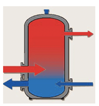
The boiler fires and charges the tank with hot water. The tank stratifies and the boiler shuts down. The load is satisfied from the tank until the boiler starts again. Sometimes the tank is added because of an issue after the boilers are installed. In those cases, a buffer tank with two ports would be added to the system.
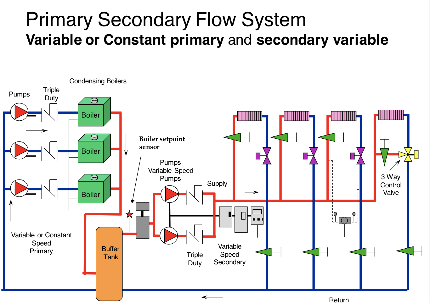
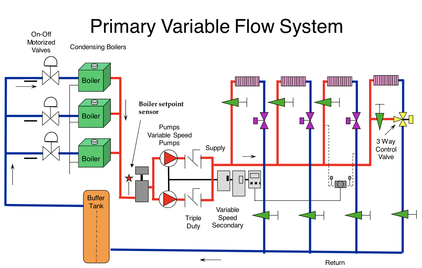
Heating System Buffer Tank Location: Primary-Variable Systems
In primary-variable systems (p-v) there is no common pipe or decoupler between the boilers and the system. The buffer tank storage is located on the return. This allows the boiler to see the hottest water and delays startup. This helps to reduce the cycles.
Please note that in both cases, there is a minimum flow rate on the secondary side to protect the pump and keep the water flowing through the tank. In the primary variable system, this flow must also meet the minimum flow rate of the operating boiler.
Now we see where the tanks should be located if they are used in a hydronic condensing boiler system. Part 2 of this series will look at the sizing criteria of buffer tanks and when to use them.
Catch up on the Hydronic Heating Buffer Tanks series below:
Part 2: Hydronic Heating Buffer Tanks – Sizing
Part 3: Hydronic Heating Buffer Tanks – Variable Primary