When we show variable speed pump curves, we also want to show the control curve. This control curve looks very similar to a system curve except it does not start at “0” GPM at “0” feet of head. Instead, it starts at “0” GPM at some value of head known as the control head. This is what the differential pressure (DP) sensor transmitter is set at. How does an engineer determine what that control head setting should be and why is it important?
It Starts with a Look at Basic Pressure Drop
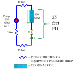
If a coil has a given pressure drop, X PSIG, at some Y GPM flow rate, then we would expect to measure Y GPM when X PSIG is measured as the pressure drop. Example: A coil has a design flow rate required of 650 GPM. At this flow rate, the coil has a pressure drop of 10 feet, the pipe and valves at the coil have a pressure drop of 3 feet, and its two-way control valve has a pressure drop of 12 feet. At 650 GPM, the total pressure drop is 25 feet. If a pump is delivering 25 feet to this zone, the flow should measure 650 GPM if the two-way control valve goes wide open. If, when the valve opens, there are only 15 feet of head available, there will not be 650 GPM flow rate. 25 feet is the control head of this coil and valve.
Constant Speed Pumps in Variable Flow Systems
Often times, we are so used to variable speed drives on pumps that we may refer to a system as “variable speed” or “variable flow” and assume they are the same thing. How does the constant speed pump operate in a variable flow system. Here is a simple example of a secondary cooling system.
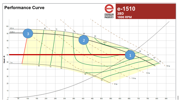
Assume the flow rate required is 650 GPM at 60 feet and any over-heading or safety factor in head calculations are across the balancing valve. If the engineer sized the pump head perfectly and the contractor installed it perfectly, the pressure drop across the balance valve is “0”. Look at the curve below. If the flow rate required is 650 GPM, then we are at design and the pump head is 60 feet (Point 1). If the two-way control valve throttles to 400 GPM, the pump moves up its curve and operates at 400 GPM at 80 feet (Point 2). If the valve throttles more and only requires 100 GPM, the pump will produce 90 feet of head (Point 3). We are getting close to shutoff or “0” GPM at 92 feet. We cannot operate at shutoff without damaging the pump, but we’ll ignore that for this discussion.
Where is all the extra head going? The two-way valve has to throttle even more to overcome the additional head.
Adding Variable Speed to a Single Coil HVAC Hydronic Application with no Feedback Loop
When we add a variable speed drive (VFD) to this pump and put a differential sensor (DP) across the pump, what will happen? If the pump is off and there is a call for cooling, the two-way valve will be open, but at what speed will the pump operate?
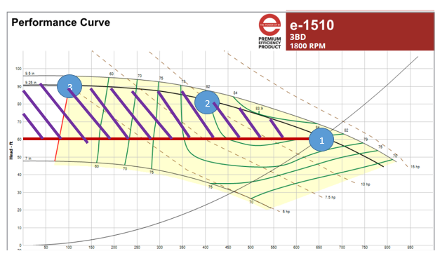
It’s hard to key in the words, “The drive is just a dumb drive”. VFDs are complicated electronic devices, but something still has to tell them where to operate. The VFD and pump are in the mechanical equipment room and the coil and two-way valve are out in the system. When there is a call for cooling, the required flow could be 100 GPM or 650 GPM or anywhere in between. In the world of DP sensors located across the pump, what pump head would guarantee there will always be enough head pressure to meet the flow requirement? The answer is 60 feet. If the design of this simple system is 60 feet, we should never need more than 60 feet from the pump. If there is no other control or feedback to the drive, then it would be safe to set it at 60 feet. Would we save energy? Yes.
The constant speed pump using the PLEV profile would cost $6,800 per year based on 24/7 operation. The variable speed pump with a control head of 60 with the DP sensor across the pump would cost $5,300 per year. The savings would be in the hatched area below.
Effects of Sensor Location at the Farthest Coil
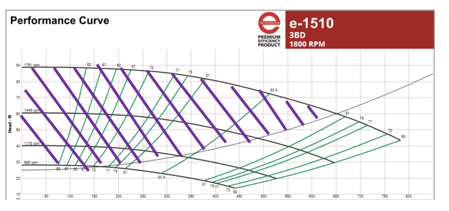
What happens if the sensor is moved out in the system so it includes the coil, two-way control valve, and interconnecting piping? Now we can take advantage of the variable pressure drop in the supply and return piping as well as the mechanical equipment room. The control head is 25 feet instead of 60 feet. The curve below shows the improved area of savings. The area under the curve is greater resulting in greater savings. The cost of operation is $3,477 per year. An additional savings of over 15% from the sensor located at the pump.
The variable speed hydronic system control head is the minimum pressure differential that the variable speed pump should product to assure the pump can provide the required flow rate to the index circuit. In hydronic systems the value of control head is the differential pressure drop in feet of head downstream from the sensor location to achieve design flow rate.
Next week the R. L. Deppmann Monday Morning Minutes will expand the control head into a system with multiple coils.

