 In the R. L. Deppmann Monday Morning Minute from June 4th we offered some tips on converting an existing over-headed constant speed pumping system to a variable speed pumping system. When the pump was throttled down to the proper pump head, the operation point was very close to end of curve. What is the issue?
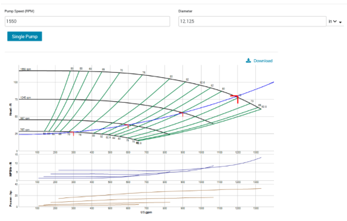
The system had a combination of three-way and two-way valves. The example I used had a pump with significant over-heading which clearly was wasting energy. The design condition was 1200 GPM at 120 feet, but the actual required head was only 80 feet.
Here is the point I made last week: Are there any concerns about the curve at the new flow and head design conditions? YES. This is a concern. The new operating point is 90% of the end of curve. Not the old 1750 RPM curve but the new 1550 RPM curve with a 12.125” impeller. This is beyond the operating point I have suggested in previous articles. The concern has everything to do with the existing balance valves and all those three-way control valves.
The Trouble with Existing Three-Way Valves
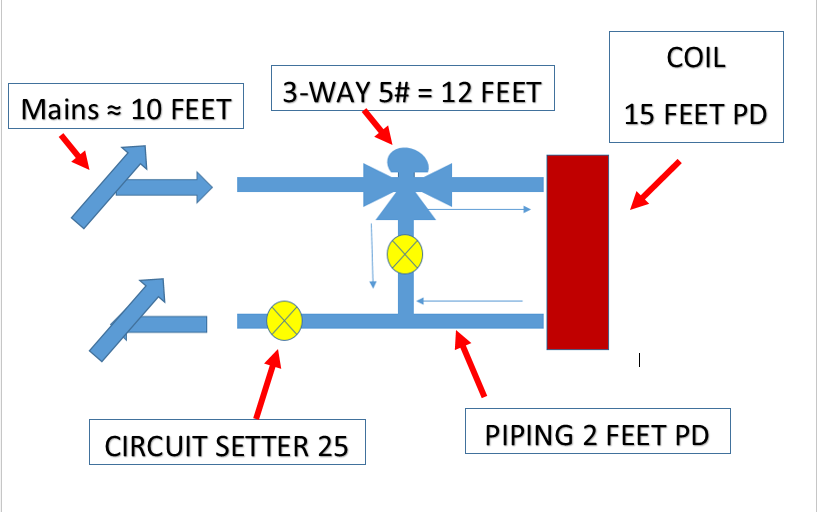
If an existing system has all two-way control valves at the terminal units, we are certain that the flow rate is dropping when the zones are satisfied. As the zone temperature is satisfied, the control valve throttles. If the control valves will close against the head pressure of an existing constant speed pump, we are comfortable that the control valves will close against a variable speed pump with lower pump head. The three-way control valves do not close off the flow rate, they simply bypass the flow. Let’s look at the representation of a coil with a three-way control valve shown below.
This could represent a single coil or a series of coils located near the secondary pumps. If we walk through the drawing, this example has a 10 feet of pressure drop in the mains from the pump to and from the air handling (AHU) unit or units; the typical 5 PSIG drop through the control valve; 15 feet of drop through the example coil or coils; 25 feet through the manual balance valve and a couple feet for piping. This totals 64 feet of head. The additional 14 feet of head is in the mechanical room.
Clearly, this 600 GPM series of coils is only half of the example flow rate of 1200 GPM, so there are more terminal units in other areas. For our example, we assume the other units are controlled with two-way valves and are also balanced.
Here is an important point when talking about three-way control valve piping
What happens if the two balance valves shown are manual type similar to the Bell & Gossett Circuit Setter? The manual balance valve in the bypass should be set to the same pressure drop as the coil and associated piping. This way the pump sees the same head pressure requirement whether the valve is full open to the coil or full open to the bypass.
What happens in the existing manually balanced system if there are no bypass valves or the bypass balance valves are full open? If the bypass balance valve is missing, the 15 feet across the bypass valve is not there. The system pump will run out on the curve and flow about 685 GPM in the bypass mode.
When the three-way valve is at 50% to the coil and 50% in bypass, there is another interesting event. The pressure drop of the control valve is less than 5 PSIG and that will also cause more flow. The three-way control valves in a part load condition may have more than the 600 GPM design. Of course, these conditions will be eliminated or significantly reduced if automatic balance valves from Griswold and Bell & Gossett were used.
You Can Monitor Flow Rate to Protect the Pump
 If the bypass of the three-way valves are not balanced, what else may be incorrect? Are the terminal units with the two-way valves properly balanced? Was the original balance of the project within 10%? These things along with the possible imbalance at three-way valves are enough to be concerned about being very close to the end of curve. That being said, there is too much energy being wasted in the existing constant speed state.
The answer is to drop the speed but don’t drop it all the way down until there is time to verify what is happening during operation. Deppmann can help you with this verification.
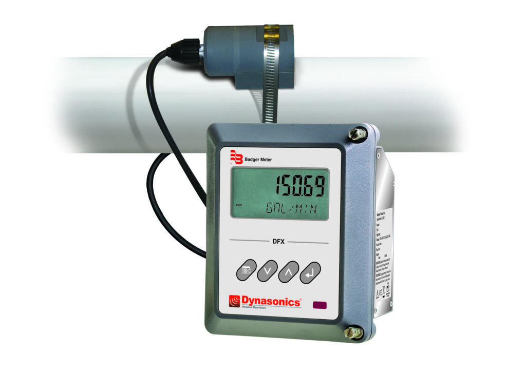
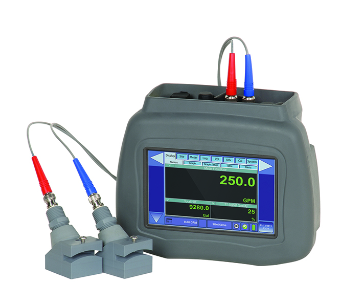
Badger Meter’s Dynasonic Brand has a portable ultrasonic flow meter that can be strapped on the outside of the pipe to record flow rates. We offer these valuable instruments for sale. This is a tool contractors may want to own. If the need is simply this one system, there is another option. Many of our sales engineers have them and use them when we are a partner in these energy saving projects.
There is more to converting constant speed to variable speed than simply slapping a drive on the pump. Give Deppmann a call and together we’ll save energy.

