Printer Friendly (PDF)
For information on the Hunters Curve Pressure Booster Prize Recipients, please check out the official announcement in the R.L. Deppmann announcements section.
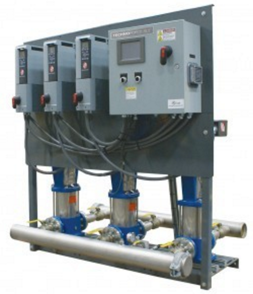
In the next few Monday Morning Minute posts, (MMM) we’ll address items that assist engineers and designers with selecting capacity for Bell & Gossett and Goulds Water Technology pressure boosters.
How to Evaluate a Domestic Water Pressure Issue
There are times in plumbing design when we receive a call that something isn’t working correctly. Once in a while, we’re surprised that we have a pressure problem in a 2- or 3-story building where we thought there was plenty of pressure. Here are some tips for ensuring that you have all of the key information you need to evaluate issues.
Pressure Analysis
Always start with an analysis of the required pressure in the building. The chances of surprises later on are drastically reduced.
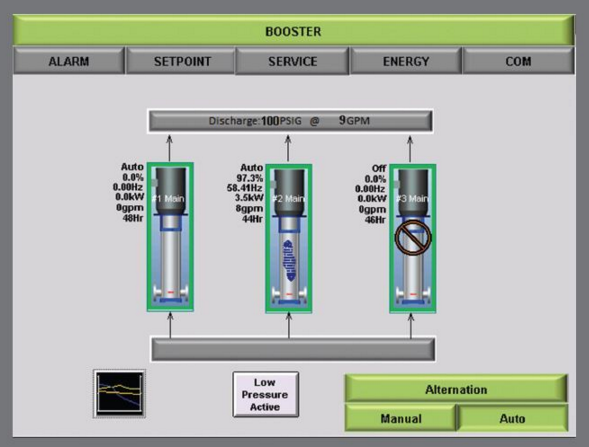
When scheduling a pressure booster pumping system, it’s always a good idea to show the discharge pressure at design flow, the minimum or no flow discharge pressure required, and the minimum suction pressure and maximum suction pressure expected. All of these should be identified as inlet and outlet conditions.
The pump head will include the required pressure boost as well as any package pressure drop losses. Of course, you may schedule that head to keep package losses to a minimum for energy conservation, but the manufacturer should be responsible to provide a required discharge pressure when supplied with a minimum suction pressure.
Data Points to Determine if You Need a Pressure Booster
Minimum fixture pressure required
This is the pressure required by the water closet, flush valve, or other fixture. It is provided by the specified valve or fixture manufacturer.
Example: 35 PSIG to a flush valve
Maximum fixture pressure required
This is normally limited by code or your internal office standards.
Example: 85 PSIG to any fixture
Your design fixture pressure required
This is the pressure you will use for the booster system calculation under load. I like to have a little extra and not design at the minimum required.
Example: 40 PSIG to a flush valve
Elevation from the booster location to the highest fixture
When determining if a booster system is required, you can start with the elevation from the incoming water supply. Once you know you need a pressure booster, be careful to identify the elevation from the booster to the top of the system.
Example: 75 feet
Elevation from the incoming water supply to the booster suction
Normally this is at the same elevation, but once in a while you may have an application where the pressure booster is located on a different floor.
Example: 0 feet
Total horizontal distance of longest run on the discharge side:
This would be the horizontal pipe on the discharge of the booster system plus the longest run on the floors to the controlling fixture.
Example: 234 feet plus a tee at 15 ft. and an elbow at 5 ft. equals 255 feet
Total horizontal distance on the suction side (TEH)
This would be the horizontal pipe on the inlet of the booster system from the incoming water line, including fittings.
Example: 20 feet horizontal plus 3 elbows at 7 ft. TEH each equals 41 feet
Maximum friction loss per 100 feet
This is the maximum pressure drop you design to in your office. It could be from charts such as those found in the B&G TEH-1096A pressure booster design manual, ASPE or ASHRAE methods, or your office standards. NOTE: This is not a place to use the B&G system syzer since that is for hydronic systems and would be too conservative for plumbing systems. You could calculate the exact pressure drop in each piece of pipe, but most engineers don’t.
Example: 5 PSIG/100 feet
Pressure drop of equipment in the system
There are items on the suction and discharge of the booster system with pressure drop.
Examples are water meters, double wall plate heat exchangers, water heaters, thermostatic master mixers, and backflow preventers. It’s good to understand what is in the system and—if the item is on the main—if it will make a difference. What is the pressure drop at design flow and minimum flow?
Example: backflow preventer with 11 PSIG pressure drop at design flow and 9 PSIG at minimum flow
A rough layout of the system
When we’re doing the analysis, it’s important to find out whether the item we’re reviewing would contribute to minimum pressure at some fixture.
Example: a backflow preventer on a ground-level cooling tower would not be a factor if a fixture at the top of the 3-story building needed 35 PSIG. A water heater and master mixer on the hot water side with a combined pressure drop of 15 PSIG will not make a difference if the cold water flush valve requires 35 PSIG and the hot water faucet does not. You still need to be the engineer and use judgment.
In our next Monday Morning Minutes, we’ll look at some examples using this information and determine the pressure required in a system.