 This week a Michigan engineer contacted me to discuss the conversion of an existing and oversized constant speed secondary chilled water pump to variable speed in order to save energy. He had concerns about the operation on the pump curve at the reduced speed. Like everything we do in retrofit projects, there was limited information. He knew there were two-way valves in the system, but there were also older three-way valves. The client was a health care facility and it is finally hot in Michigan. We could not shut the system down or drive the system to full bypass to check operation at various loads. What concerns should we have?
The Present Condition
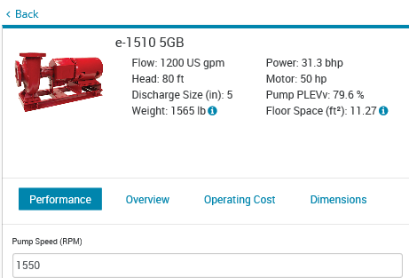
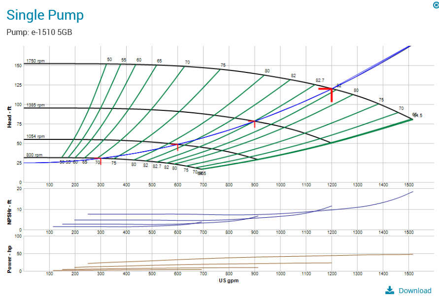
The pump was an existing B&G e-1510-5GB Base Mounted End Suction Pump with a capacity of 1200 GPM at 120 feet with a 50 HP, 1750 RPM motor. The discharge triple duty valve was severely throttled. The engineer did some calculations and determined that the actual required pump head was about 80 feet at the 1200 GPM design flow rate.
The system had two-way and three-way valves at terminal units. There was a question of whether the balancing valves were adjusted over the years. There was also a concern that the bypasses of some of the three-way valves did not even have balancing valves. Important questions to ask when evaluating existing systems.
The Variable Speed Condition
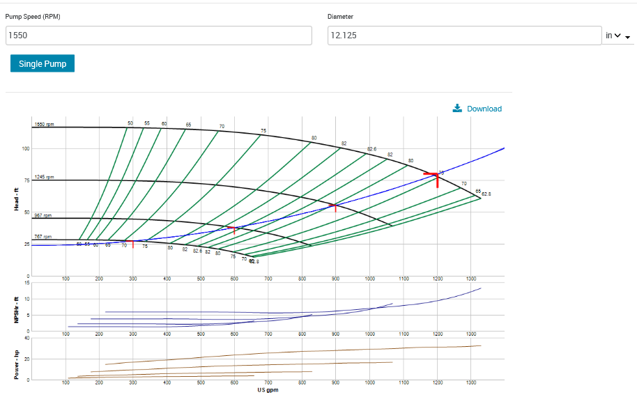
The obvious energy savings was the horsepower we would save by dropping the pump head to around 80 feet and opening the triple-duty valve. We ran the selection in variable speed mode and determined the curve would look like the one shown here.
Without trimming the impeller, the design condition of 1200 GPM at 80 feet of head would require we drop the maximum speed of the variable speed drive to 1550 RPM. Clearly, we will save a lot of energy by doing this. What is the downside?
Concerns When Changing from Constant Speed to Variable Speed
There were several concerns we discussed about this project. Let’s take them in order.
- The Motor. The pump is newer and the motor meets the NEMA premium efficiency motor standards, so it should be acceptable to operate on variable speed variable frequency drives.
- The Coupler. The coupler is a center drop out coupler with a black EPDM sleeve. If it was the orange harder Hytrel™ coupler sleeve, it would have to be replaced. When operating with a VFD, the pump coupler needs to be EPDM.
- Will variable flow cause issues with equipment? The system is a primary-secondary configuration with constant flow primary pumps on the chillers. The secondary system has two-way and three-way valves so it is already variable flow. No issue here.
- Will there be some flow when all the two-way valves go closed? Yes, since there are three-way valves in the system.
- Does the variable frequency drive (VFD) have a bypass starter? The drive is not existing. R. L. Deppmann will be supplying the specification for the drive and we will NOT have a bypass starter. If there was a bypass starter or an across the line starter, it will bypass the drive. When it bypasses the drive, the pump will operate at 1750 RPM or full speed. We know the pump head is too great and way oversized. The triple duty valve will be opened and the excess head pressure will cause the pump to run out on its curve. The additional flow rate may damage terminal units and may damage the pump. If there was a bypass starter on this drive, we would recommend trimming the impeller.
- Are there any concerns about the curve at the new flow and head design conditions? YES. This is a concern. The new operating point is 90% of the end of curve. Not the old 1750 RPM curve but the new 1550 RPM curve with a 12.125” impeller.
This last point is also the starting point for the next R. L. Deppmann Monday Morning Minutes.


