Printer Friendly (PDF)
 It is important to check the single pump operation when selecting parallel pumps for multiple constant speed cooling tower pumps.
In the last R. L. Deppmann Monday Morning Minute, Constant Flow Cooling Tower Pumps & Variable Frequency Drives (VFD), we explored the savings advantage of variable frequency drives (VFD) on a single pump application. Before we do the same for multiple condensers and pumps, let’s look at an important issue of balance and pump selection.
Multiple Constant Flow Condenser Pumps and Head Loss
Here is a representation of a multi-tower and condenser system. We will assume a requirement of constant flow through each condenser if it is operating.
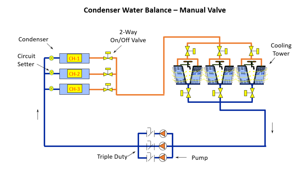
We have three condensers and three parallel piped cooling tower pumps. We will assume all three will operate when called upon. Each pump is rated at 700 GPM design flow rate with a B&G 3DS-6B triple duty valve.
In the application shown above, the pump head consists of the fixed pressure drop of the condenser with its piping and its circuit setter (example 20 feet), the tower height (example 10 feet), the fixed friction loss through each pump’s piping (example 5 feet), the friction loss through pipe and valves (example 10 feet), an allowance for strainer fouling (example 5 feet), and a safety factor (example 10 feet). Another consideration is that some towers may require a fixed pressure entering the nozzles. The total pump head for this example is 60 feet.
These are constant speed, staged pumps. The 15 feet for fouling and safety would end up across the triple duty valve as excess pressure drop. This example will result in the triple duty balance valve 50% closed. The chart in Part 1 of this series shows a savings for a single pump operation with a single chiller if it operated 24/7 for 180 days.
Parallel Pump Selection with Multiple Condensers
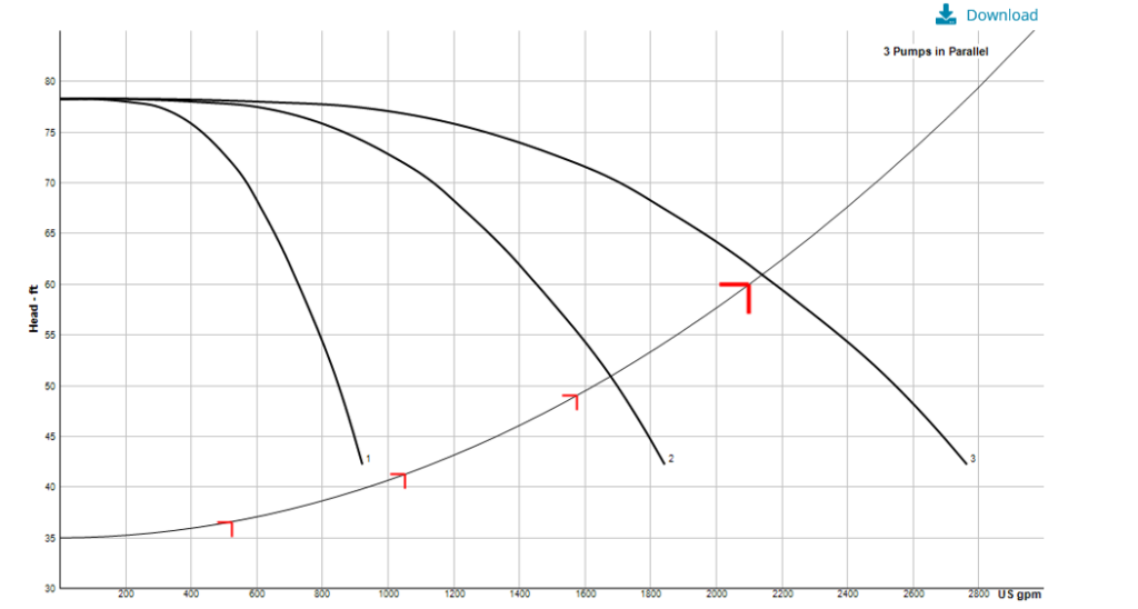
There will be no flow until the height of the tower is overcome, 10 feet in our example. The flow is constant through each condenser so the 20 feet through the condenser and the 5 feet minimum at the pumps are also fixed. The system curve would start at 35 feet.
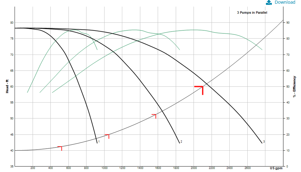
The best pump efficiency is a B&G e1510-4BD at 15 HP, 1770 RPM. When we look at the parallel curve, we may want to go to a bigger, less efficient pump because we are off the curve with the single pump.
The engineer may choose a larger pump which is left of the best efficiency point to avoid this issue. There is another option. Rather than give up efficiency and increasing the horsepower, we could just increase the circuit setter pressure drop by 5 feet.
Balance Valve Selection at Multiple Condensers
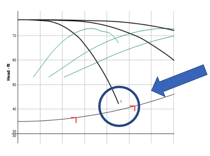
In the example above, we have 15 feet of excess pump head anyway so we will have 5 feet of it across the circuit setter and 10 feet across the triple duty valve. Notice above, the pump will run out on its curve with one pump operating. The engineer should verify the additional flow rate, in our case, this flow rate is about 850 GPM, is within the acceptable limits of the condenser and tower. Don’t forget that the additional flow, if acceptable, will impact the net positive suction head available (NPSHa) for the cooling tower pump.
Assume the velocity is too high and we still want to stay constant speed. Change from the B&G circuit setter to a Griswold or B&G automatic flow limiting valve at each chiller. Make sure the pressure range is low. The starting number of the pressure range will be added to the pump head. Use a 1-20 PSID or 2-32 from Griswold or a 2-60 control range from Bell & Gossett.
Make sure you select the exact valve and schedule it since it may be a different size than the pipe. In our example of 700 GPM in 6” pipe, the B&G Circuit Sentry might be the better choice since it will be line size. Do not accept automatic flow limiters with a higher starting control range unless you included that much pressure drop in the pump head calculations.
We will tackle the balance procedures of this system and revisit the use of variable speed drives (VFD) in the next two blogs.