Printer Friendly (PDF)
 Oftentimes an engineer or contractor is contracted to remodel or add to an existing building. During the site visit, they find a pump tag with pump model numbers that they can’t find in the online catalog from B&G. How do you sleuth out what they have? It is not unusual for the R. L. Deppmann customer service team to get calls daily regarding pumps installed in the 1960s, 1950s, and even the 1940s. How does the engineer or contractor identify what is existing and estimate the flow and head?
What Information Can You Get?
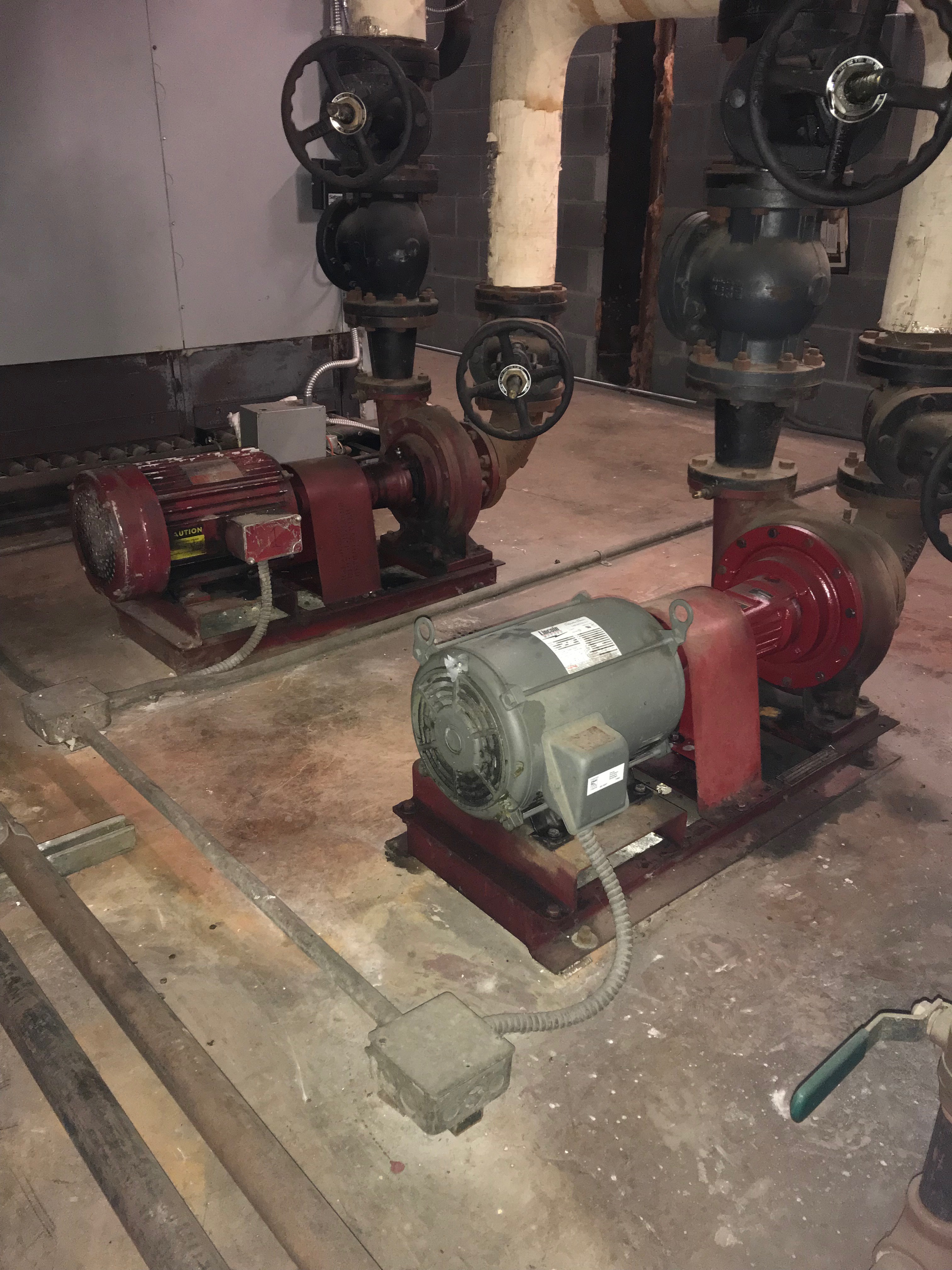
I started with a huge assumption in the statement above: “find a pump tag”! Often times there is no tag on the pump and only a tag on the motor. If that happens, you can often zero in on the pump model by other means, such as the casting number. We addressed this in a past R. L. Deppmann service tip of the month, How to Identify a Bell & Gossett Pump. Whether you have the tag or used our helpful hints to obtain a model number, what does the model number mean and how do I estimate capacities?
B&G 1510 Pump Model Numbers
Pumps installed in the 1970s and after are usually called 1510 pumps. The recent e-1510 designation was incorporated in the last few years to indicate the use of the newer, high efficiency stainless steel impeller designs. Most prior models had bronze impellers, although they were available with other materials. You may actually find pumps from the 1940s and 1950s called 1511, 1512, and 1515 series. Just give us a call since you will not find these on the internet. We will look for the quill and ink papyrus catalogs of the olden days.
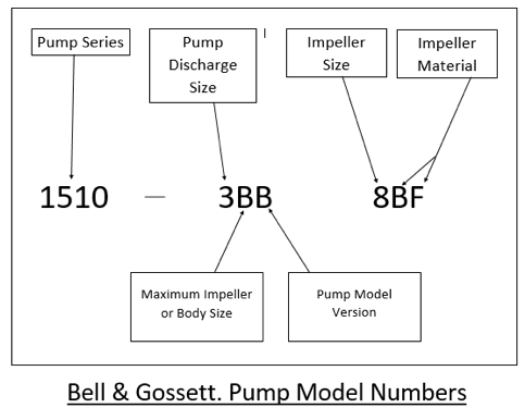
A typical model number could be, for example, 1510-3BB – 8BF. Let’s break this down step by step. We start with 1510 which is the pump series. The 1510 is a base mounted end suction flexibly coupled pump. It could also be, for example, 1531 which is a foot mounted end suction close coupled pump. The old pump might look similar to a 1510 but start with a “U” which means it was a 1510 style pump with oil lubricated bearings.
The next number is the pump size. The “3” indicates a 3” discharge size. This is not the pipe size which may have an increaser on it but the actual pump discharge size. The suction size is normally one size larger.
The next two numbers are critical. The first “B” in our example is the volute or body size and the maximum impeller. In general “A” is a maximum 7” impeller, “B” is 9.5”, “E” is 11”, and “G” is 13.5”. You may find some others such as “C” but they are rare and your B&G representative can look them up.
The last number is the version. This really makes a difference when trying to determine capacities. If there is no letter or the letter is “A”, this is the first or second offering of the pump. B&G prides themselves on the longevity of the pumps and constant improvement of efficiency. As a result, every time they change the internal construction to provide improved pump curves and efficiency, the last number changes.
How committed is B&G to improved efficiency? Let’s look at an example. Take a 1510-3BB pump and look at the curves.
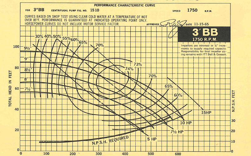
1510-3BB has a best efficiency point of 75% at 380 GPM
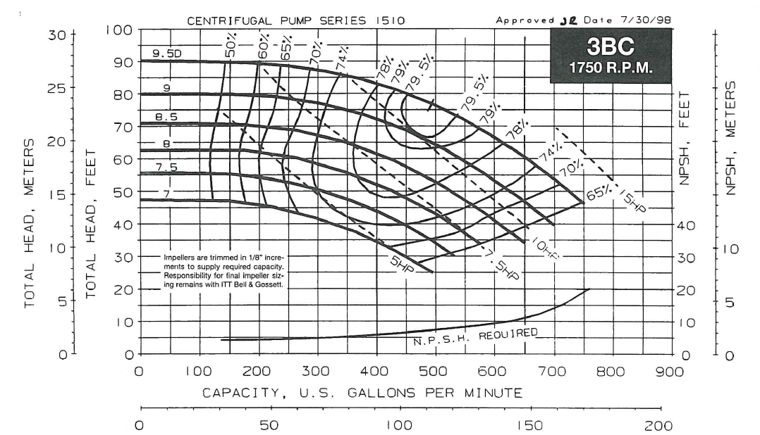
1510-3BC has a best efficiency point of 80% at 490 GPM
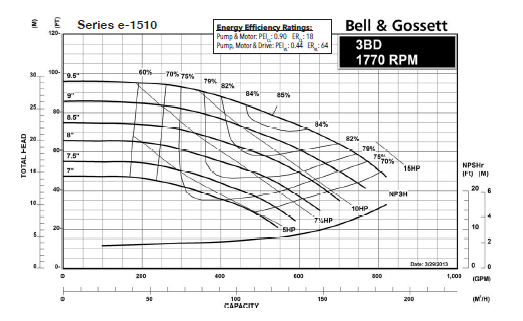
e-1510-3BD has a best efficiency point of 84% at 530 GPM.
B&G shows a strong commitment to constant efficiency improvement. One thing that makes me smile is customers who say the B&G pumps haven’t changed in decades. They say that because the pumps look similar. Where possible, B&G tries to keep dimensions about the same in case there is a replacement need, but just because the pump looks the same does not mean it is the same.
“B&G shows a strong commitment to constant efficiency improvement”
The last set of numbers show the impeller size and material. With this, you can identify the curve and estimate the flow and head.
Estimating Flow and Head Without the Impeller Size
If the impeller size is known, it is easier to estimate the flow rate. If the impeller is not known, then we can rely on some rules of thumb. You can always set the controls in the fully open position and take gauge readings. R. L. Deppmann also has Badger Dynasonics transit time flow meters which mount external to the pipe for flow measurement. Our sales engineers have them available to assist you.
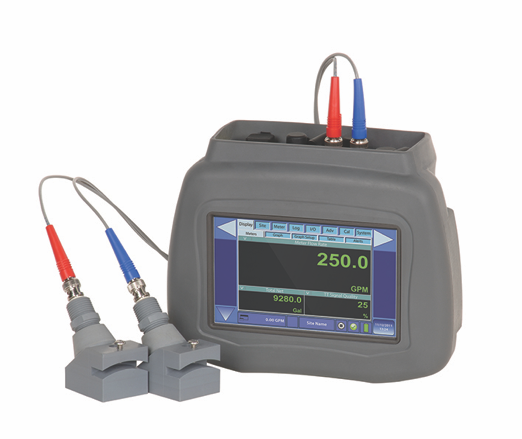
Badger Dynasonics Portable Meter
There may always be cases where an engineer or contractor used a different sizing method, but most of the time the following will be close enough.
First look at the pipe size. Until the recent ASHRAE 90.1 energy standard changes, engineers often used the B&G system syzer wheel and selected in the white “pie” which is 1.5 – 4 feet of pressure drop per one hundred feet.
Next we look at the pump curve and the horsepower. Today an engineer might select a pump at as much as 85% of end of curve. Back in the 1960s and 1970s engineers were more conservative and selected to the left of best efficiency of a pump. They also used non-overloading horsepower similar to today. With this information and looking at smaller or larger curves we could estimate what the pump capacities might be.
Example of Estimating Flow and Head
Assume the pump tag was missing but you followed the helpful hints on the video link above and found you have a 1510-3BB and you identified the motor as 7.5 HP at 1750 RPM. The pipe mains are 4” and the pipe down to the pump is 4”. What might we estimate the flow rate to be?
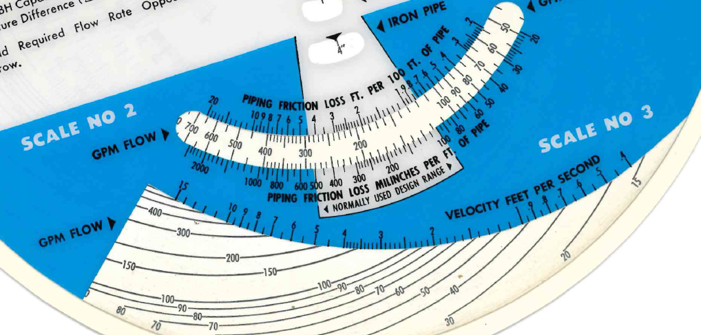
The B&G system syzer for 4” pipe would lead us to assume the pump was selected between 160 and 280 GPM. That is a wide range. When we look at the curve above, we would estimate an 8.25” impeller maximum for non-overloading operation. Here is where a bit of knowledge goes a long way. If the flow rate was between 160 and 250 GPM, a 1510-2.5BB, the next smallest pump, would be a great selection. One could argue the 1510-2BB pump could work, but 1970 engineers did not like to have the pump more than two pipe sizes smaller than the pipe because of velocity noise. Noise trumped efficiency in the olden days. Therefore, based on all of this, I would assume we are between 250 – 270 GPM at about 60 feet. Yes, engineers rounded the head calculation just like today.
Just Call Your B&G Representative
This may seem like a lot of intrinsic knowledge. You may not have the time. We know a lot about hydronic systems, so just call our inside customer service or contact your outside engineer salesperson. They can do the work for you.
We could also look at the boiler BTUH to see if that aligns with our estimates. Of course, you may have a steam to water heat exchanger and the client wants to look at changing to hydronic boilers. How would you figure the load? We estimated the GPM this week using the pump model. The next R. L. Deppmann Monday Morning Minute will look at estimating BTUH from an existing B&G SU steam to water heat exchanger.