Printer Friendly (PDF)
Over the last few weeks the Monday Morning Minutes posts have looked at pumping issues with multiple condensers and pumps. One of our most-received questions was, Why do I need cooling tower outlet on-off valves if I have an equalizing line? Why do we see outlet on-off valves on almost all jobs in North Carolina and only half the jobs in Michigan and Northern Ohio?
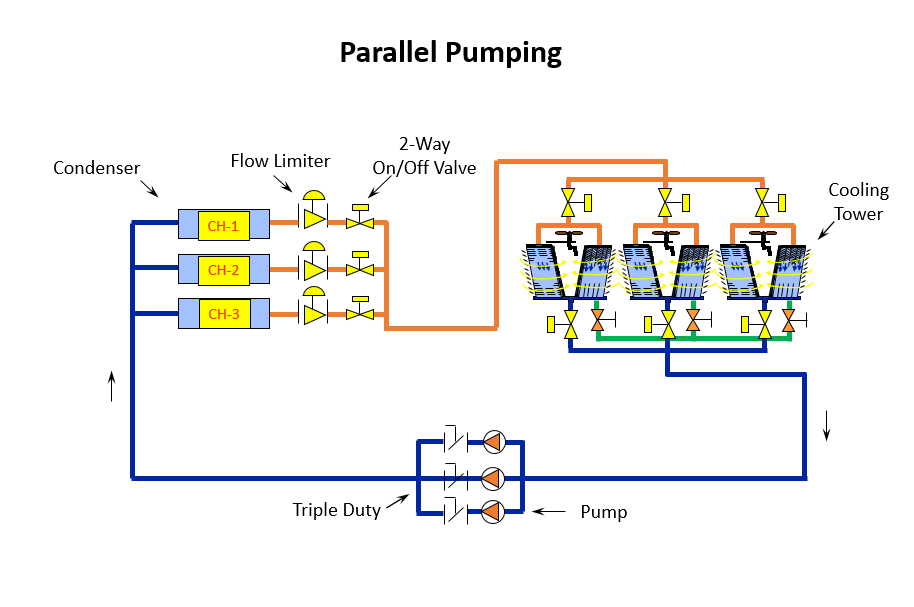
Using 2-Position Outlet Control Valves on Multiple Cooling Tower Designs
Let’s start with the need for the on-off control valves on the tower outlet and stick with the example we’ve used for the last several weeks. The example is a condenser water pumping system with a design of 800 GPM per tower for a total of 1600 GPM and a third tower as standby.
In a part load condition, some tower inlets will be closed and one will be open. In our example, the open or active tower will have 800 GPM flowing to it and the inactive tower will have zero GPM since the on-off 2 position inlet control valve is closed.
The tower basins, without control valves, may be modeled as follows:
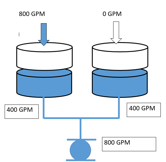
The pump is attempting to pull 800 GPM from a tank or basin and both basins are open to atmosphere. With the exception of slight piping differences, the flow out of each basin will be approximately equal. The flow through the tower and into the basin will not be equal, since one inlet is closed. The result is that the tower basin in the inactive tower will start using makeup water very quickly but the makeup is not 400 GPM. This drop in water level could cause the inactive basin to empty and possibly suck air into the pump. The system pump will air lock and stop pumping. Meanwhile, the tower in operation overflows.
Sizing the Equalizing Line Between Multiple Cooling Tower Basins
Does the equalizing line solve the problem mentioned above? We checked with four tower manufacturers and they all size the equalizing lines the same way. The equalizing line is a gravity flow pipe between all of the tower basins. It’s sized based on a flow rate equal to 15% of the largest tower design flow rate. In our example, the total flow rate of each cell is 800 GPM—so the equalizing line flow rate is:
800 GPM x 0.15 = 120 GPM
The pipe size is based on the calculated flow rate with the motive force being the gravity flow caused by 1” differential—and 1” differential is .0833 feet.
We could use the Bell and Gossett system syzer for this calculation. Let’s assume in our example we have 20 feet of piping, two elbows, one tee, and the entrance and exit opening pressure drop. What pipe size would we need to flow 120 GPM of water through all of that with 1” pressure drop?
The Bell and Gossett system syzer is a great tool. Here’s what I did:
- Select a pipe size and entering 120 GPM in the “Flow/Pressure Drop” tab.
- Go to the “Length/Pressure Drop” tab and click on the help with TEL button and enter the pipe length and fittings.
- Change the pipe size until the pressure drop is less than .0833 feet.
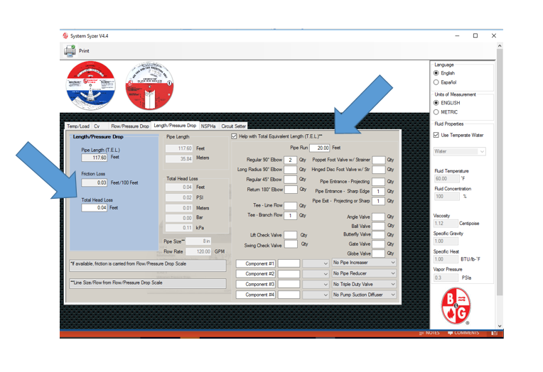
The result was that an 8” pipe should be used for the equalizing line. I was surprised by the amount of total equivalent length (TEL) that the entrance and exit openings caused. In the past, this is a pressure drop I have ignored when calculating cooling tower suction piping pressure drop. I found a note in a BAC tower article reminding the engineer not to forget the entrance and exit pressure drop. It added about 40 feet of TEL! Thank you BAC—I won’t forget it in the future.
Remember: the correct way to size the equalizing pipe is to contact the tower manufacturer. The pipe size should never be less than the opening size of the tower you select.
Control Valves: North vs. South
So why does it seem that there are fewer control valves on tower outlets in Michigan vs. North Carolina?
It doesn’t take an engineer (sorry for the pun) to know that if a basin is flowing 120 GPM in and 400 GPM out that the level will drop and the makeup float will call for makeup water. For this reason the tower manufacturers want 2-position on-off control valves on the outlet of the tower basis when using multiple staged towers.
So why is it that Norm Hall sees so few installations with 2-position outlet valves in Michigan and Chad Edmonson sees so many in North Carolina? One reason is weather! It gets well below zero in Michigan and not as bad in North Carolina. The engineers in Michigan put basin heaters in the specification but some engineers are still nervous about having a basin with no flow in the winter.
What’s different?
- If they have the room, they could use a cold well tank mounted indoors, which eliminates the need for the 2-position valves as well as the basin heaters.
- The 8”pipe in the calculation above has a pressure drop of .28 ft./100 at 400 GPM, so maybe there’s a combination of less pipe length, different fittings, a drop in basin water level greater than 1”, and the required makeup water difference. (A lot of ifs!)
- If they oversize the equalizing line to 10”, the friction loss is .09 ft./100 at 400 GPM.
- Maybe they didn’t know better and there are problems and the tower manufacturer works with the contractor during commissioning to solve the problem.
Or maybe we need to understand why the 2-position valves are there and follow the tower manufacturer’s instruction.
This is all about cooling tower installations, so we defer to the manufacturer of the tower you have chosen to specify for specific details and requirements. Next week we open the fall season with the misunderstood topic of humidifiers.