Printer Friendly (PDF)
In humidification systems, we know that steam absorption distance is important. We also know that various distribution methods have different required absorption distances. How do I determine which humidifier to choose to match my available absorption distance? This week we’ll show you how.
Getting the Humidification Specification Right
The absolute best way to ascertain that you have adequate steam absorption distance is to use sizing and selection software. A good choice is the DriCalc program from DriSteem. By entering a few values, including the entering and leaving air conditions, you not only get equipment options, but also the corresponding absorption requirements. These requirements should be noted within the plans as a performance specification. The manufacturer can and should decide from there exactly how many rows of dispersion tubes and what orifice sizes will be required to meet the specification.
Finally, it’s important to place the dispersion assembly in a location that will best facilitate absorption. That’s going to be the point where the air is the warmest and there’s sufficient duct length.
The figure below shows a duct layout with potential options for humidifier location (A, B, C, and D).
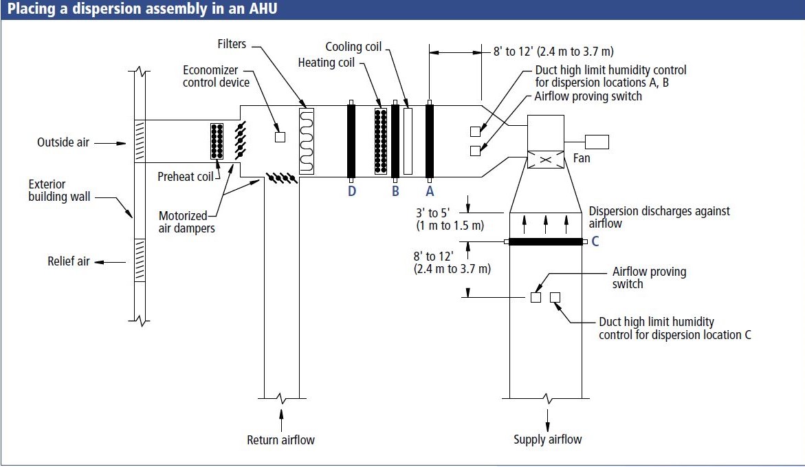
In this case, point A is the best choice for the dispersion assembly location. This because it is downstream of the heating and cooling coils, which will provide laminar flow with heated air. If there isn’t enough space for A, we could consider B, but this could cause an issue during changeover periods if the cooling coil is turned on.
As a third choice, we could look at location C if there is adequate space to install the dispersion assembly. But we would have to be careful of turbulent flow, which could impact the steam absorption distance. All three of these locations occur after the heating coil, so the air is at its warmest. Point D would be a poor location do it because of the cold air stream.

Humidity Safety Checks
Notice that there’s a duct high limit humidity sensor positioned after the dispersion tube to make sure that humidification does not exceed setpoint. We recommend using a modulating high limit transmitter for this safety. This allows the high limit to operate in conjunction with the room humidistat. If we start approaching the high limit setting in the duct, we would start reducing the humidifiers output.
Another option to consider is temperature compensation control. With this option, the humidifier is provided with a temperature transmitter that continually monitors the interior window glass temperature to calculate the dew point. If the window temperature falls below the dew point, we would automatically decrease the relative humidity setpoint so that moisture doesn’t form on the windows. That’s a clever way to make sure you never exceed suitable humidity levels within the space.
Dispersion Assembly Near an Elbow
Lastly, let’s consider where to put the steam dispersion assembly if we are near an elbow. The figure below shows possible locations (A or B).
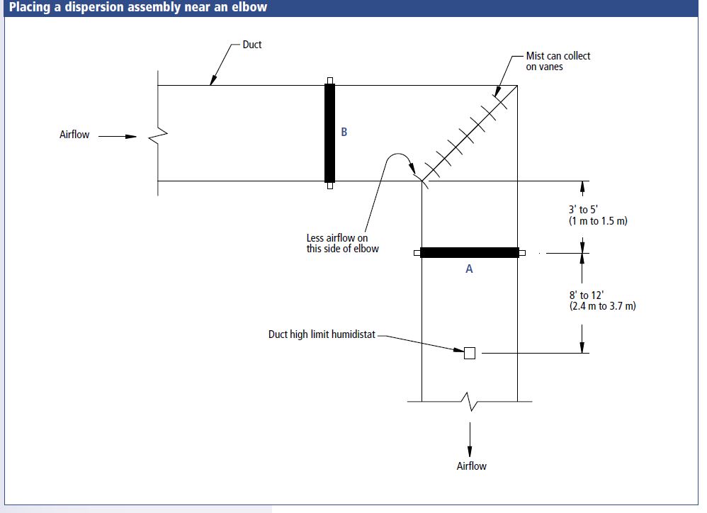
In this scenario, location A is the best choice. This is because better absorption occurs downstream of the elbow. If there isn’t enough straight duct at this location, then B can be considered—but we must be careful to not wet the turning vanes. If B is chosen, we highly recommend installing a multiple tube unit to make sure you have complete absorption. In either case, it’s best to discharge the steam against or perpendicular to the air stream to provide the best possible absorption.
See the rest of this series here:
- Humidification Basics: Why We Humidify in Building Design
- Humidification Basics Part 2: Mastering Humidification Terms
- Psychometrics Made Easy: Humidification Basics Part 3
- Calculating Natural and Mechanical Loads: Humidification Basics Part 4
- Calculating Humidification Loads for Economizer Cycle Systems: Humidification Basics Part 5
- Steam Isothermal Humidification: Humidification Basics Part 6
- Load Calculation Using Dristeem DriCalc: Humidification Basics Part 7
- Adiabatic Humidification: Humidification Basics Part 8
- Importance of Water Quality and Type: Humidification Basics Part 9
- Steam Absorption Distance: Humidification Basics Part 10
- Types of Isothermal Humidifiers: Humidification Basics Part 12
- Pressurized Steam Distribution: Humidification Basics Part 13
- Steam Humidifier Distribution Panels for Short Absorption: Humidification Basics Part 14
- Steam Humidifier Condensate Handling: Humidification Basics Part 15