Variable frequency drives (VFD) take the incoming power and convert it to DC power inside the drive and then create their own three-phase output power. Therefore, the rotation should be checked every time a VFD is commissioned. The VFD needs to also be checked for proper rotation when in bypass operation. There are other types of bypasses in the market, but the most common type of VFD bypass is the three-contactor bypass type.
Below is the factory authorized method that Deppmann uses on the VFD with the three-contactor bypass. We prefer to physically change the phasing by changing the wiring instead of using the programming in the HVAC drive to change the rotation. You can change rotation in the VFD programming, and it is fine to do so. The problem with doing it this way is that if for some reason the drive loses memory or is hard reset and goes back to factory defaults, the rotation could be backward when the driven equipment is restarted. Damage to rotating equipment could happen.
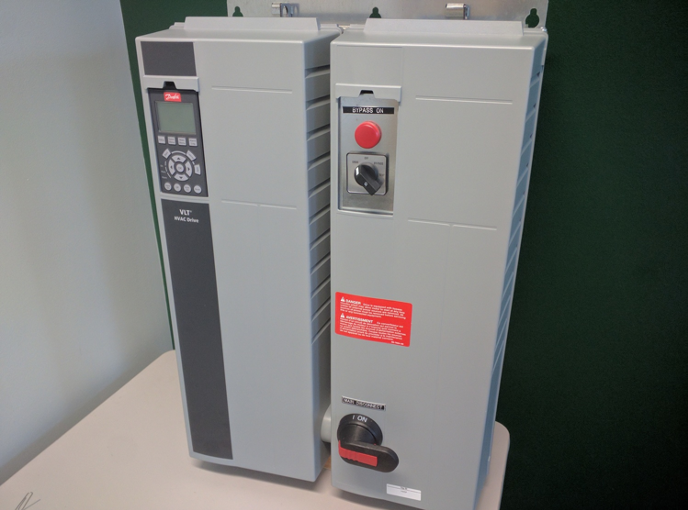
Fig. 1 Picture of Danfoss HVAC Drive with Three Contactor Bypass
Steps to Check Rotation in HVAC Drive with Bypass:
1. Check motor rotation direction in HVAC drive control as follows.
- Put panel in drive mode.
- Hand start drive at the minimum speed (see drive specific operating instructions for details).
- Confirm directional rotation.
- If incorrect, stop the drive, remove power, and lockout.
- Reverse connection of any 2 of 3 motor leads at the output side of the Thermal Overload as shown in blue on Fig.2. Do not change incoming power leads.
- Remove the lockout and apply power.
- Confirm directional rotation.
2. Check motor rotation direction in bypass as follows.
- Momentarily bump motor in bypass.
- Confirm directional rotation.
- If incorrect, stop the drive, remove power, and lockout.
- Reverse connection of any 2 of 3 input power leads at the load side of the drive disconnect shown in orange in Fig. 2. You may also need to lockout the feed to the VFD from the building power supply panel. Do not change motor leads!
- Remove lockout and apply power.
- Confirm directional rotation.
Safety is always our number one concern and this type of work should always be done by a qualified person. Always follow state and local codes. LOCKOUT & TAG OUT any potential energy sources before beginning any changes.
The first step is to make sure that the equipment the VFD controls is ready to operate and is safe to do so. The second step is to turn on the power from the building’s power panel to the drive and verify the voltage is correct at the line side of the drive disconnect. If correct, you can proceed to turn on the drive disconnect and then turn the selector switch to drive which will power up the drive and the display will power up too.
Please reference the IOM from the VFD manufacturer to make sure the speed is turned down, then push the hand button which will start the motor rotating. Refer to step 1 above and Fig.2 below. Observe the direction of the rotation of the motor shaft and verify the direction of rotation of the driven equipment is correct. If the direction is correct in drive mode, proceed to step 2 above and reference the IOM if needed. If the rotation is incorrect, follow the procedure in step 1D to correct the rotation for drive mode. Always LOCKOUT potential energy sources before working on the drive.
Next check the rotation of the motor shaft in the bypass mode. Make sure the motor is stopped in the drive mode, then momentarily bump the selector switch to bypass and observe the rotation of the shaft direction. If it is correct you are all set. If the direction of rotation is not correct, refer to Fig. 2 in orange and follow step 2C to change the direction of rotation for the bypass mode. Always make sure the power and any other forms of energy are LOCKED OUT.
After all, steps are followed and rotation is correct in both drive mode and bypass mode you can undo the LOCKOUT procedure and put the equipment into service.
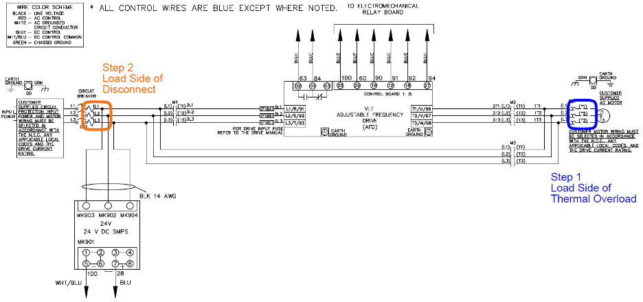
Fig. 2 Typical Danfoss Three Contactor Bypass Wiring Diagram
R.L. Deppmann Can Help
If you have any questions regarding this procedure, please reach out to any of our startup and warranty technicians. They can be reached by calling 1-800-589-6120.