Printer Friendly (PDF)
 Waterside economizers per ASHRAE 90.1-2013 and 2010 shall provide up to 100% of the expected system cooling load at outdoor air temperatures of 50°F dry bulb/45°F wet bulb and below. We understand the cooling tower water supply temperature to a water economizer will vary with the weather. The chilled water supply temperature from the water economizer heat exchanger will also vary with the weather. What effect will warmer chilled water supply temperatures have on the cooling capacity of the system?
Chilled Water Load in the Winter Months
ASHRAE 90.1-2013 states the waterside economizer shall provide up to 100% of the expected load at outdoor temperatures of 50°F dry bulb and below. This statement will require the waterside economizer to be active a good amount of the year. As an example, here is some dry bulb weather data for Lansing Michigan. The data is from Weather Spark.
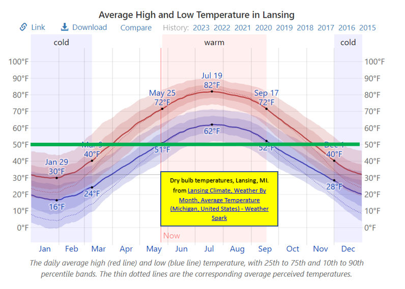
I added a green line showing the 50°F dry bulb. We can see there is a great amount of time the economizer will be required. The design may include an air economizer and a water economizer. Both are used to satisfy the cooling load without the activation of the chiller.
Commercial and institutional buildings may require cooling in the winter and shoulder months. The supply makeup air is colder, and we are less concerned about the incoming heat from the outdoor temperature. The engineer will account for load based in internal heat gain of people and equipment. In general, there is a good chance that the actual load during these months will be less than 50% of the summer design chilled water load.
Chilled Water Supply Temperature
In part 3 of this series, Water Side Economizers Part 3: Cooling Tower Temperatures, we showed a graph of cooling tower supply temperatures based on the wet bulb temperature. We will use the graph from part 3 in an example system in Lansing, Michigan.
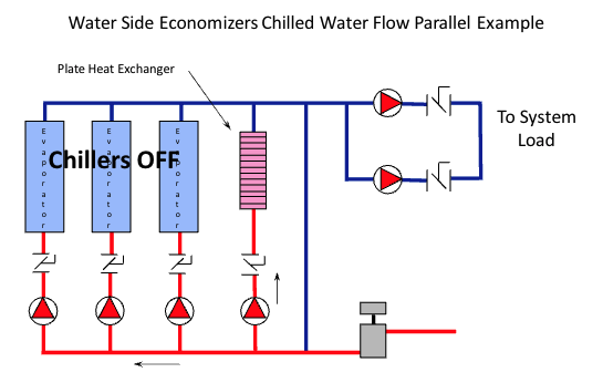
Assume we have a water economizer heat exchanger in parallel with the chillers. What chilled water supply temperatures can we expect from the economizer with no chiller operating? Rather than provide way too much data for all possible daily temperatures, we will look at our example using the average monthly temperature from 3:00 to 4:00 PM.
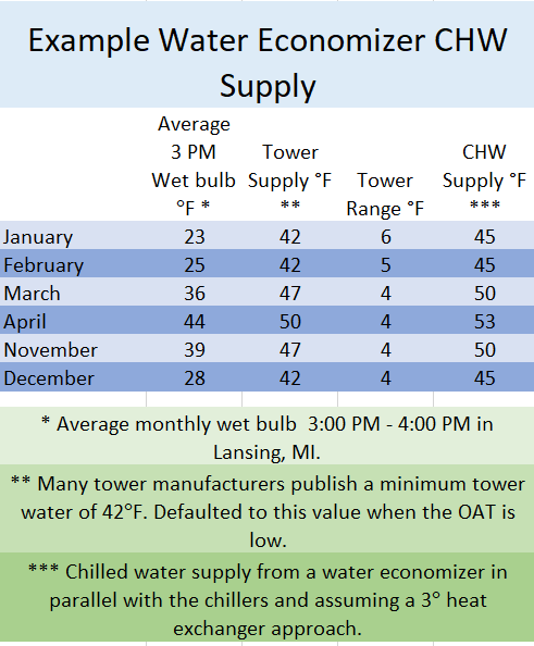
Please note a couple of items before we use the chart above. There are a significant number of tower manufacturer limitations when using a tower in the cold winter months. One limitation, for most, is a minimum water temperature of 42°F. When the wet bulb temperature and tower approach would result in a temperature too cold, we default to the 42°F minimum.
The heat exchanger used as the water economizer is a plate & frame heat exchanger. The heat exchanger approach is different than the cooling tower approach. The heat exchanger approach is the difference between the cooling tower water supply into the heat exchanger and the chilled water supply out of the heat exchanger. They are capable of very low approaches. We used a 3°F approach for this example.
The result is a water economizer chilled water outlet temperature ranging from 42 to 53. If the system was designed for 45°F chilled water, what happens as the supply temperature goes up?
The Effect of Warmer CHW Supply Temperatures
Warmer chilled water supply temperature will reduce the coil output. There will be a small percentage of sensible loss but a huge loss in the ability of the coil to handle the latent heat.
How are the terminal unit capacities affected if warmer water is supplied to them? We know there will be some loss of capacity but how much? I turn to some information provided by Gil Carlson in one of his many talks to industry groups.
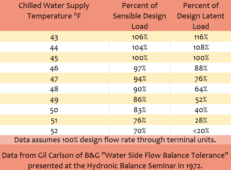
We can see the percentage of sensible heat will drop some amount as the supply temperature goes above 50°F. The latent heat is almost eliminated at 52–53-degree chilled water supply. These numbers may not present a problem in most Michigan and northern Ohio buildings. The engineer should be aware of the reduction and verify it is not an issue before proceeding with the parallel water economizer solution.
Chilled Water Flow Rate in Economizer Cycle
The control valves remain in control of the chilled water flow rate. If the space is satisfied, the temperature controls will throttle the control valve and reduce the flow rate.
We see above that the coil will produce less BTUH capacity than it was designed for when the chilled water supply temperature is increased. If the supply temperature of the chilled water is 50°F, the chart above would indicate about 83% sensible capacity at full flow rate. That said, the temperature controls will continue to adjust the control valve position to maintain the space temperature. When 83% of the sensible load is too much for the requirement of the space, the control valve will throttle, and the pump flow rate would be reduced. The chart above shows the maximum capacity and not the required capacity.
The chart states that “Data assumes 100% design flow rate through terminal units”. I would suggest that in today’s HVAC operation, 100% design flow rate should occur very rarely if reset strategy is not employed. Almost all HVAC coils should be seeing reduced load (lower entering mixed air conditions) during economizer operation and the goal of the economizer is to be sized for the load at 50db/45wb which implies lower load at the coils.
The use of reset, however, also increases the flow demand. But for any load, delta t is inversely proportional to the flow rate. Lower delta t with lower return water temperature unloads chiller(s) that are operating (with integral operation intended by 90.1). Also, while the chart is helpful to see % of design loads with increased temperature at 100% design flow, it should also be recognized that coil capacity at part load is higher than the proportional flow rate. It may be helpful to see the HVAC coil performance curve vs. flow rate. Here is a curve from the ASHRAE 2020 handbook, chapter 46, page 46.9.
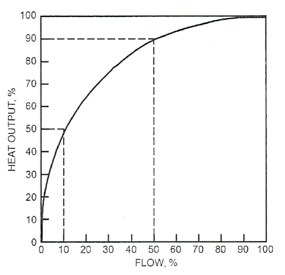
Assume, using the previous example, that the mixed supply water temperature to the coil is 50°F. Assume also that the required capacity is not 83% sensible and 40% latent but only half of that. The ASHRAE chart tells us that at a requirement of 50%, the flow rate required would be 10% of the design.
Simultaneous Chiller and Economizer Operation in Parallel
If the economizer is piped in parallel with the chillers, the supply water to the system will be a blending of the two temperatures. This may cause havoc with chilled water reset controls.
In this parallel piping method, we recognize that when the chiller is operating with the water side economizer, the supply chilled water will be a blend of the heat exchanger outlet and the chiller outlet. If the reset sensor is downstream of the chiller and the waterside economizer, it will be sensing the mixed temperature and react as if the chiller was not responding. Obviously, the coils will receive this mixed water temperature as the supply and react as shown in the Gil Carlson data shown on the chart above.
The effect of the varying chilled water supply temperature in a parallel waterside economizer application may affect the controls and space comfort. There is a better way to pipe the water side economizer to improve overall results. We will address these strategies next week.
PART 1: Free Cooling Heat Exchangers
PART 2: State Energy Codes
PART 3: Cooling Tower Temperatures