Often times, the engineer is replacing the existing secondary pump in a system with a combination of two way and three-way control valves. How do we take advantage of the ECM High Efficiency Smart Circulator Pumps in this application? Let’s step back and look at three-way valve operation, then apply the Ecocirc-XL to the system in this week’s R. L. Deppmann Monday Morning Minutes.
Three-Way Valve Operation and Limitations
Three-way control valves may be diverting or mixing depending on how they are ported and controlled. The sketch below shows a three-way diverting valve system. As the temperature from the terminal unit or coil is satisfied, the flow rate is reduced in the coil and the flow is diverted to the bypass. When the coil is completely satisfied, the resultant return temperature to the mains is equal to the supply temperature. When calling for full heat or cool, the return temperature to the system is equal to the design outlet temperature from the coil. In between full load and no load, the return temperature varies depending on the flow rate needed in the coil.
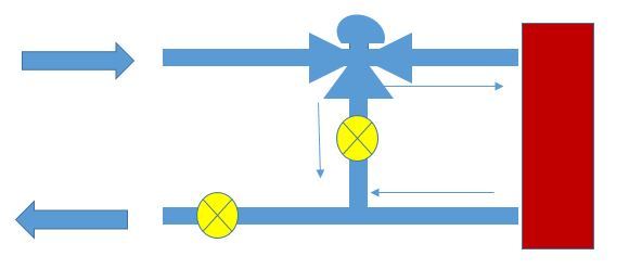 A simple example follows. Let’s assume the design flow rate in a heating coil is 20 GPM with a 180°F supply and a 140°F return. As the room temperature is satisfied, the three-way control valve bypasses flow and the return water temperature back to the return main rises toward 180°F. The return water temperature is 160°F when half of the flow is through the coil and half is in bypass. The use of three-way valves normally means the flow rate is constant and the return temperature varies.
When the owner of this system turns to their consultant for energy saving ideas, this constant flow system is yelling out “Pick me Monty!” (If you don’t know what that is, ask someone with gray hair). Assuming the boiler can handle reduced flow or no flow, it seems all we have to do is close the bypass valve. That is where we may run into a three-way valve limitation.
Three-way valves have a limit to how much pressure they can close against depending on the construction and type of control mode (air, electric, self-contained). They were designed to bypass or mix flows and not to close tight. As a result, the valve will leak through when it tries to close completely providing unwanted flow and heat transfer. Hydronic systems may allow a great deal of heat transfer at lower flow rates. If the three-way valve leaks when the controls are telling the valve to close, there could be uncomfortable room temperatures. This could be the case if the bypass balance valve is closed.
Application of the B&G Ecocirc®-XL Smart ECM Circulator Pump in Three-Way Valve Systems
In a primary-secondary system, the source flow rate is separated from the terminal flow rate by the common pipe. If the system is not primary-secondary, the engineer should find out if the reduced flow rate would cause an issue with the boiler or chiller. The following shows a system set up for constant flow. It would not be prudent to reduce the flow rate in this system without understanding the effect of the minimum flow rate through the heat or cool source.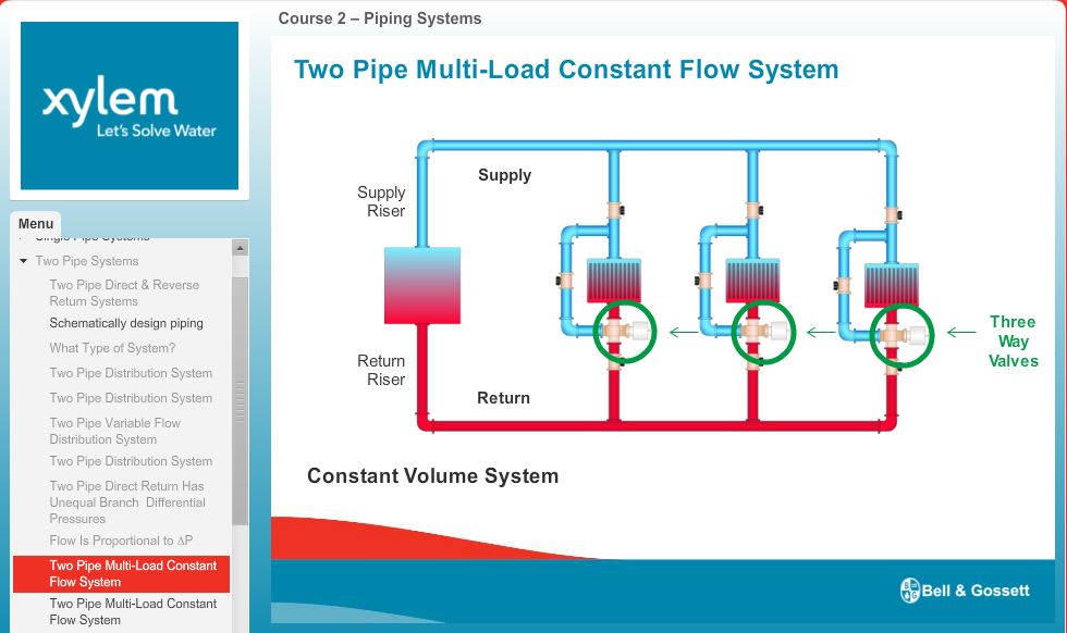
As a side note, this slide is cut from the B&G E-Learning website where you can take online classes with quizzes for credits.
As the temperature rises, we know that flow rate is being bypassed somewhere and therefore, we do not need as much flow. In this case, the engineer could reduce the speed of the pump in response to the return temperature. This could be accomplished using a drive and temperature sensor. On smaller systems, the ECM smart circulating pump would also work well.
A word of warning is important at this point. Why do most systems use pressure differential instead of temperature? The temperature is a blend of the return temperatures from all of the coils. THIS ONLY WORKS IF THERE IS LITTLE DIVERSITY BETWEEN THE TERMINAL UNITS! If one coil is asking for a lot of flow rate while others are not, the mixed return temperature will reduce the speed of the pump. That reduced speed may not have enough head to provide full flow to the coil that needs it. I’ll address that in a later R. L. Deppmann Monday Morning Minute.
I am suggesting the B&G Ecocirc-XL in this application because the ECM technology lends itself to smaller systems with smaller head loss and those systems tend to have less diversity. The Ecocirc has all the circuitry needed for a quick addition of variable speed. The temperature sensor is an option supplied with and wired directly to the pump. No external building management system is needed. If the pump happens to be located on the return you will not even need the external sensor since the pump has an internal sensor built into it.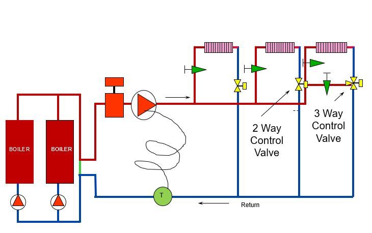
The return temperature will vary even more if the system has boiler reset. The Ecocirc-XL has an internal temperature sensor. Once the external sensor is installed, the pump operation can be changed to differential temperature. Nothing more is needed. The setup changes slightly.
What happens if there is a combination of three-way and two-way valves? In this case, the system will have varying flow and varying return temperature. Bell & Gossett has you covered. By using the differential pressure mode in combination with the differential temperature mode (ΔP-ΔT), the engineer has a pump that will follow the pump head control line along with the response to temperature changes. As shown below, there is no additional equipment needed.
Electrical Diagrams and Control Sequence for ECM Smart Circulator Pumps with Three-Way Valves
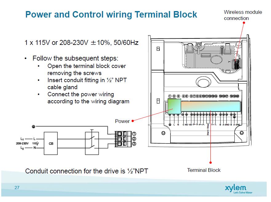
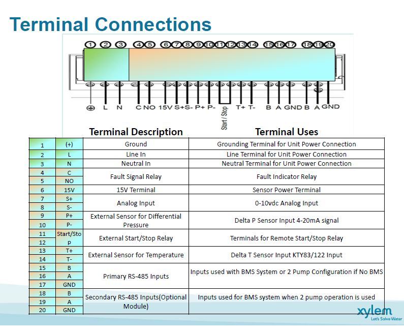
Electrical diagram is the same as other applications.
Sequence of Operation
Primary Heating/Cooling Pump (insert tag) shall be enabled by a call for heat/cool (enabling the start-stop contacts 11-12 through a remote relay). The pump speed shall be varied in response to the external RTD wired to terminals 13-14. The RTD shall be supplied by the pump supplier. The pump shall vary speed in response to the change in return water temperature. In heating systems without reset, the pump shall reduce speed on a rise above the design return temperature and increase speed on a reduction in temperature. In heating systems with temperature reset the pump shall reduce speed on a rise in differential temperature above the design and increase speed on a reduction in temperature differential. In chilled water systems, the pump shall increase speed in a rise above the design return temperature and reduce speed on a drop in temperature. Fault indication will be shown on the pump and may enable an analog input BMS fault indicator thought terminals 4-5 if shown in documents.
Next week, the R. L. Deppmann Monday Morning Minutes will look at the use of ECM Smart Pumps in larger domestic water recirculation systems.
**Always read the complete installation and operation manual before beginning any work.

