Printer Friendly (PDF)
 In last week’s R. L. Deppmann Monday Morning Minutes, I reviewed the Bell & Gossett Circuit Setter manual balancing solution and suggested that it is a Good solution.
I also reviewed the Griswold K-valve automatic balancing solution and suggested that it is a Better solution.
The newest addition to the art of balancing in domestic hot water recirculation systems is the thermostatically controlled balance valve. This may be the Best solution for the plumbing engineer to review. Let’s look at why I believe the Bell & Gossett Temp Setter™ thermostatic balance valve will be the Best solution for domestic hot water recirculation systems.
What is the Bell & Gossett Temp Setter Balance Valve?
The Temp Setter is a thermostatically controlled balance valve. When we set the flow rate in a manual or automatic balance valve, we are attempting to cause a flow rate that will result in the design “end of runs” temperature. The flow balance indirect method works, but results in constant “design” flow 24/7. There are codes and standards that indicate the recirculating pump should be shut off at times, but this is in direct conflict with concerns about stagnant water conditions.
The Temp Setter has a field adjustable range of 98°F to 150°F. The valve is located at the end of each branch hot water supply just like the traditional balance valve. Once set, the valve will adjust or throttle to maintain the temperature set point. If the temperature reaches set point, the valve will throttle to maintain the temperature. If the temperature is below set point, the valve opens. When the valve throttles, it will never close completely allowing for non-stagnant flow.
Why measure flow rate when water temperature is what you desire?
Specifying and Sizing the Temp Setter Balance Valve
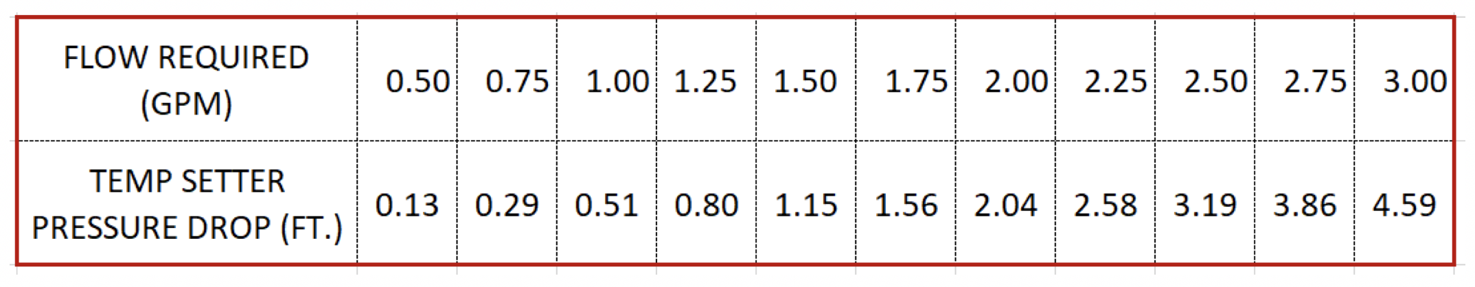
Sizing of the Temp Setter is very easy. The valve is available in 1/2” and 3/4” sizes and with or without the disinfecting bypass option. Whether the line size is 1/2’ or 3/4”, the Cv is 1.27, so we could use the B&G System Syzer to calculate the pressure drop. I provide a handy chart below for quick reference.
B&G Temp Setter TS-1/2”, TS-3/4”, TSB-1/2”, TSB-3/4” Pressure Drop
There is no reason to show the flow rate on the drawings. Here are four simple steps for the engineer:
- Show a symbol for the valve at the locations the recirculation line starts just as you would for a manual balance valve.
- Create a detail showing the valve with isolation service valves around it. Show the temperature set point on the detail.
- Determine whether you want the valve only or the valve with the bypass option and specify your choice.
- Indicate in the valve specification section or the test and balance specification whether the plumber or balance contractor is responsible to set the valve to the correct temperature.
What Temperature Should I Specify for the Temp Setter Balance Valve?
The temperature setting for the balance valve depends on your design. ASHRAE Guideline 12 indicates the minimum supply temperature for hot water should be 140°F with thermostatic valves at the fixtures. The same guideline suggests a minimum of 124°F for the hot water return temperature. If your design is based on different temperatures, identify that temperature in the documents.
What Is the Bypass Option and Should I Specify That Option?
ASHRAE Standard 188 refers to disinfection procedures which may include circulating 160°F water to kill any Legionella.
How do I do that with a valve set at 124°F? Visit the R. L. Deppmann Monday Morning Minutes next week to find out.