 How many times have you, as an engineer, looked at a number of pump curves and passed up a few because you did not like something about the selection on that curve? Today we look at pump curve selections close to the end of the curve and offer some tips to help you make a better decision with pump selection.
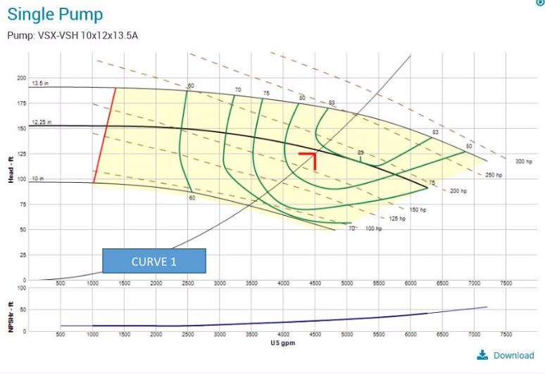
Look at Curve 1 below. Let’s assume you selected this pump. You specified the design GPM, head and 200 HP. The pump will be variable speed with a DP sensor at the far zone. You specified the minimum pump efficiency of 82.2%. You liked the fact you had “room on the curve to move.”
The submittals come in and you get a competitive submittal similar to Curve 2 below. What happened?
The pump in Curve 2 meets the flow, head, horsepower, and is even 3% better in terms of efficiency; but you are not happy. The obvious answer is that in the competitive bidding environment, pump Curve 2 is less expensive. How can you avoid this? Should you have selected the Curve 2 option at the time of design?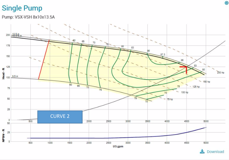
Why Should I Avoid End of Curve Pump Selections?
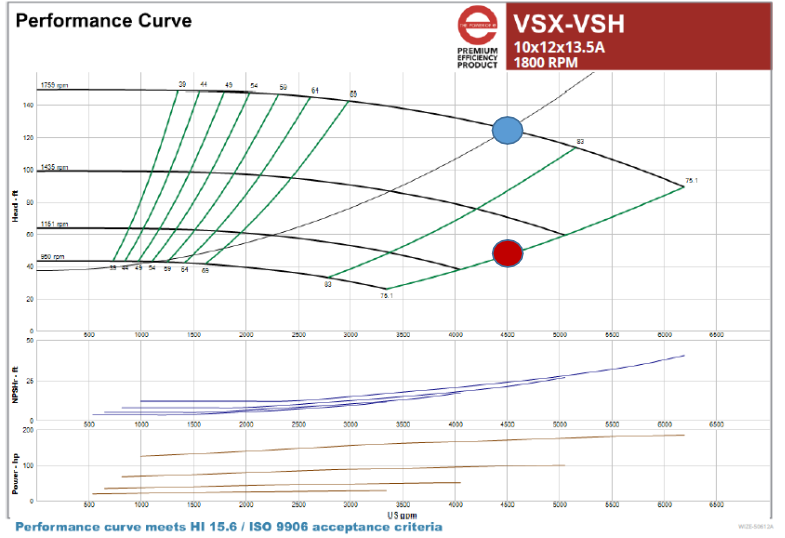
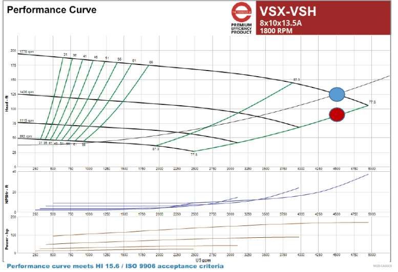
Let’s look at the variable speed curves for the two pumps. For this example, I chose a control head of 37 feet. The first curve, shown below, is the pump you selected. The second curve is what was submitted.
The blue dot in the curves above is the design point. The red dot represents the minimum speed the pump may run at full flow rate before operating off the end of the curve. If I have over headed the pump by only 20%, I will be at the fail-safe point of operation where pump damage may occur. ASHRAE 90.1-2013 requires a proportional balance and the setting of this maximum speed or trimming the impeller. Either way, this pump is in trouble. Read more about this in an earlier R. L. Deppmann Monday Morning Minute titled HVAC Hydronic Pumps: Impeller Trimming with a Drive (VFD).
Solution:
The manufacturer of the pump in Curve 2 is willing to guarantee it will operate at the selection point but it is too close to the end of the curve. B&G guarantees a pump can operate at any point on the published curve. This assumes the point will not drift to the right. Maybe you are concerned about the over heading mentioned above. Maybe you are concerned about drift as control valves open and close. Maybe you are concerned about velocity. There are two ways to handle this. Specify a maximum percentage of the published curve. Selection 1 above is 70% of the end of the curve flow and Selection 2 is at 93%.
Specify:
Norman Hall suggests: Pump selections shall meet the scheduled capacities and be selected so the scheduled design flow rate is not greater than 85% of the published end of curve flow rate for the impeller selected at design speed. Extrapolations beyond the published curve will not be accepted.
For the everyday systems, these criteria will protect you from surprises during the submittal stages. As always, we are ready to review our customers’ selections before the project is out for bid.
Next week we will look at Bell & Gossett’s ESP-Systemwize and its use in pump selections.

