Printer Friendly (PDF)
 In the last R. L. Deppmann Monday Morning Minutes I defined the difference between flat curves and steep curves in a hydronic pump selection. I also explained why flatter curves are better in hydronic systems. Steeper curves for process applications is a request from a time gone by. Using today’s pump controls, a flat curve will provide control and also reduce filter and strainer maintenance. It’s not magic, it’s all about pumps and drives. Today, we will look at applications in industrial process systems where filters or strainers can be expected to fail.
Old School Constant Speed Pumps in Dirty Systems
Long ago…., OK, just 20 years ago, most industrial plant water pumps were constant speed. The design engineer had to deal with high-pressure drop, full flow strainers, and filters which could have a low 2-3 PSI pressure drop when clean and a 15-20 PSI drop when it was time to change or clean them.
Let’s explain using an example assuming we have a requirement to pump 800 GPM.
- Let’s assume the system with the clean filter has a pump head requirement of 120 feet.
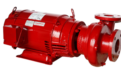
- The process engineer selects a B&G e-1531-5A close coupled 3600 RPM pump with a severe duty TEFC motor.
- The engineer was willing to accept the shorter pump life of a close-coupled pump and a 3600 RPM motor because the plant has a capital improvement requiring new pumps every 4-5 years.
Here is the constant speed curve we will analyze:
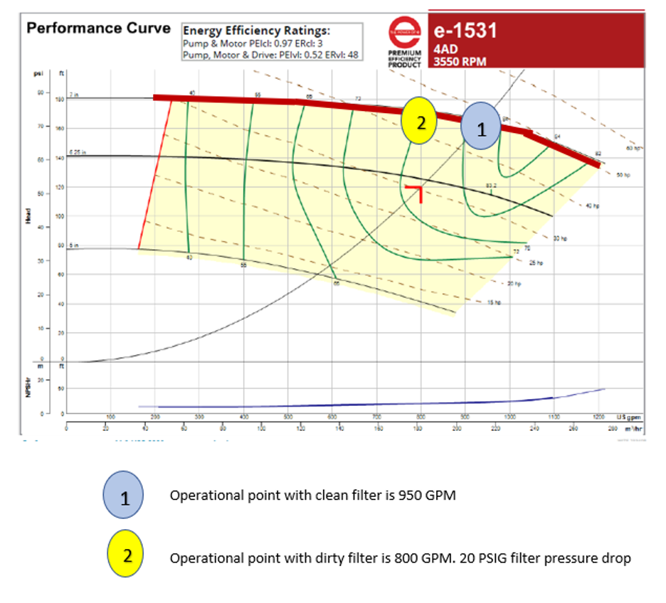
In order to allow for the filter clogging and time between maintenance, the engineer would then select and purchase the pump for 800 GPM at 170 feet increasing the motor to 50 HP and impeller to 7”. This would result in the pump overflowing when the filter was clean. It would then back up on its curve as the filter clogged. When the filter had 20 PSI of drop, the filter would be cleaned. Few people were worried about the extra flow rate. More was always better.
Today: Variable Speed Pumps in Dirty Systems
We are more energy conscious today. The flow control and energy control are both better with the use of a variable speed drive.
- The engineer will still select the pump for the extra pump head and larger impeller.
- The pump is still selected for 800 GPM at 170 feet.
- We know that head calculation has a 50-foot allowance for clogging of the filter.
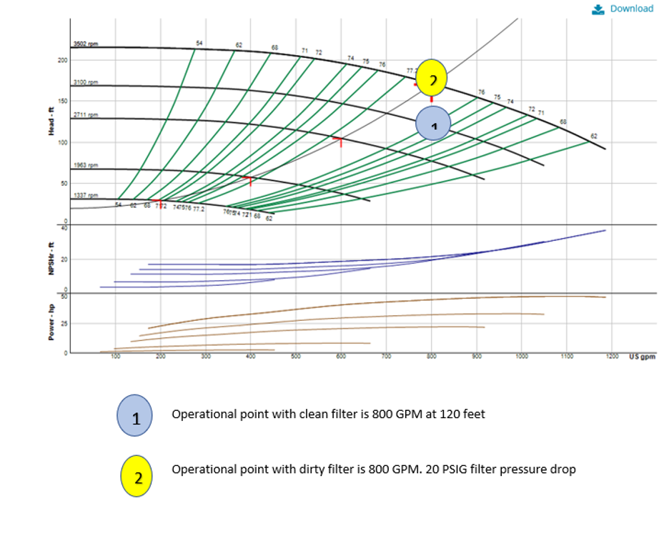
The energy savings is great. The flow rate remains constant, so the plant operation is very happy. You simply set a differential pressure (DP) sensor transmitter across the existing supply and return and set it for 120 feet or 53 PSIG. The pump will operate at 3100 RPM clean and 3500 RPM when it’s time for maintenance. If the engineer is designing the plant, there is even more energy to save by properly placing the DP further out in the plant.
This story also has a place in the world of HVAC. In tower systems, the use of a variable speed drive may be used like process systems. Visit our Parallel Pumping in Condenser Applications: Automatic Differential Pressure Control (Part 3) blog for a quick introduction.