 We are gathering input from the last R. L. Deppmann Monday Morning Minutes asking for your feedback on the potential to “not follow the rules.” Sometimes system pressure issues can be overcome by thinking about the system in a different way. Today, we look at our high-rise example with an eye on reducing the sizing of expansion tanks from a re-design perspective.
Re-Cap of the Issue: Expansion Tanks Are Just Too Big
Here is the story. An existing 8 story, very large old structure will be gutted and renovated with retail and restaurants on the main level. The floors are 12 feet high and the heating equipment will be located on the main floor. The engineer is attempting to stay away from pressures over 120 PSIG. The pumps have 150 feet of head. This large system will have 12,000 gallons of water.
In part 1 of this series, we reviewed the effect of locating the tank in three different locations:
- Location “A” was the traditional main pump suction location. The result was (4) B&G 48” x 100” tanks.
- Location “B” was on the return at the top of the system. This result was smaller tanks but an issue with the combined weight of tanks and water.
- Location “C” is pumping into the point of no pressure change. This breaks the rules, and we are gathering input about the pros and cons. The good point was the tank sizes. It dropped to (2) 48” x 83” tanks. Is there a way to drop the sizes of the expansion tanks but not break the rules?
Using Primary Secondary Systems to Reduce the Expansion Tank Size
Our main issue with tank sizes in location “A” was the size of the tanks. The engineer wanted to keep the pump discharge pressure below 120 PSIG. With a cold fill requirement of 46 PSIG and a maximum pump discharge pressure of 120 PSIG when the system is hot, there is only a 9 PSIG allowable pressure increase. The expansion tank parameters are 12,000 gallons of water with a 46 PSIG fill pressure and a maximum pressure of 46+9=55 PSIG. The fill temperature is 40⁰F and the maximum temperature will be 180⁰F.
We could increase the pipe size selected to severely reduce the pump head. This would solve the pressure problem but drive the cost of the project to the point where the owner would not go ahead.
We discussed the system with the engineer. It turns out most of the air handling equipment was located on the bottom four floors. The total flow rate was 3000 GPM. Only 15% of the flow rate was used for the remaining upper floors
What would happen if we installed a heat exchanger and pump set in a small room on the fourth floor?
Design Using a 4TH Floor Mechanical Room
If we split the system, using heat exchangers, the flow rate of the fourth-floor pumps, serving upper levels, would be 450 GPM total. The head of those pumps would be about 40 feet. The main pumps would then change to 130 feet of head at the original flow rate of 3000 GPM. The fill pressure and maximum pressure of the main expansion tanks would also change. The tank volume required would be slightly less. The main mechanical room would now have (2) B&G B-1400 tanks at 36” x 98” each.
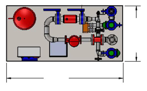
The fourth-floor mechanical room would then utilize a hydronic package with B&G plate heat exchangers. The complete package solution would be a ProPak Solutions heat transfer package using B&G ecocirc-XL smart variable speed pumps and be about 8 square feet of required area.
The important thought is the real advantage of splitting high-rise systems into a couple of zones if it makes sense from a working pressure perspective.
Next week I will share some of the input coming in about the point of no pressure change rule.


