 The flow balance of a hydronic system is a critical component in the commissioning of an HVAC hydronic system. The common balance and flow measurement valves we use to accomplish the balance of the system break down into categories of manual and automatic balance. Today, the R. L. Deppmann Monday Morning Minutes looks at the types of valves and the advantages and disadvantages of both.
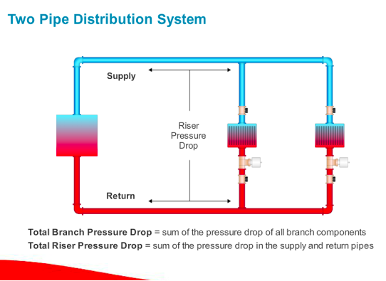
In the prior MMM, I showed a system out of balance with more flow rate than needed going to the zone closest to the pump. Take a look at the simple sketch below and assume the first terminal unit has less pressure drop than the second one. At the design flow rate, the pressure drop from the pump discharge through the first zone and back to the pump suction is less than the same trip through the second zone. As a result, the water takes the path of least resistance and flows more through the nearer zone.

Image courtesy of Bell & Gossett eLearning Center: http://bellgossett.com/training-education/e-learning/
The goal of the balance valve is to increase the pressure drop in the zone flowing too much water. If we cause the right amount of pressure drop or pipe restriction in the first zone, the flow will decrease in that zone and increase in the second zone.
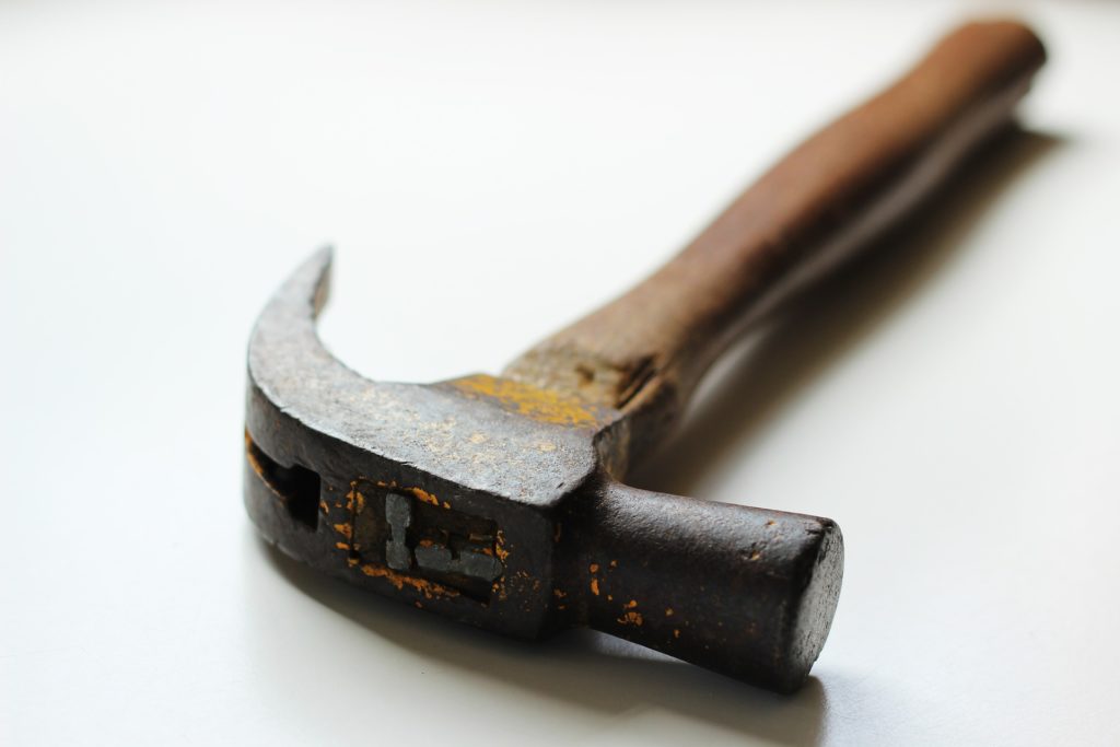
You could use a hammer to reduce the area in the pipe but you only get one shot and you can’t read the flow rate to see if you achieved your goal!
Manual Balance Valves
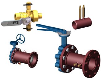
Ball and Butterfly Valves: The Simplest Balancing Valves
The first balance valve used in hydronic systems was the variable orifice balance valve. If you think about it, plug valves, ball valves, and butterfly valves are all variable orifice balance valves. If you throttle the valve, the hole the water goes through is reduced in size and therefore the pressure drop increases.
Way back in the 1940s and 1950s, this was the balance valve used. The contractor throttled the valve and used thermometers and pressure gauges to determine if they were close enough to call the system balanced. It was the art that started the Balancing Contractor Industry.
Today, we may still use these devices as balance valves, but we couple them with a separate, properly installed flow measuring device.
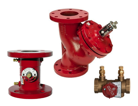
Variable Orifice Balance and Flow Measurement Valve: The Bell & Gossett Circuit Setter

Image courtesy of Bell & Gossett: http://bellgossett.com/flow-balancing/manual-balance-valves/circuit-setter-plus/
The Bell & Gossett Circuit Setter was the first combination balance and flow measuring valve to have national distribution. It is a ball valve or globe valve with ports across the valve and charts to read the throttled differential to flow ratio depending on where the calibrated dial is set.
ADVANTAGES:
- Probably the best advantage of this device is how recognizable it is. The industry can recognize the Circuit Setter installed 3 years ago or three decades ago. B&G has re-engineered the product over time but kept the flow characteristics the same. The chart you use today is the chart you can use on the same size older valve.
- Much lower straight lengths of pipe are required for accurate measurement (3 diameters upstream and 1 downstream).
- High repeatability and 5% accuracy.
- In stock everywhere.
DISADVANTAGES:
- The prime disadvantage is reading flow rates less than ¾ GPM while requiring high-pressure drops. You can set the valve to read less than ½ GPM but there is not much throttle capability.
Constant Orifice Balance and Flow Metering Valve: Griswold Quickset and B&G Venturi
The venturi type balancing valve is different from the circuit setter. A modified venturi is a small orifice with smooth entrance and exit paths. It is modified because a true venturi would be significantly longer. This is two devices joined together. The differential is read across the fixed orifice. The flow is throttled across a separate ball or butterfly valve. The differential across the orifice is read in inches.
Some might argue the pressure drop is significantly less. For example, a balanced Quickset might read 40 inches while the circuit setter reads 40 feet. This is a little misleading since the equivalent of the 40 feet was throttled across the ball or butterfly valve. Even full open, the ball valve portion of the Quickset has some pressure drop that remains unread.
ADVANTAGES:
- Easier to read during the balancing. These devices may have a different sized opening or “throat” areas. So the inside of the flow meter changes depending on the flow. This allows the contractor to read enough differential for a more accurate setting.
- Griswold’s Quickset has a unique design that allows for no pipe diameters required after an elbow. Other brands will have 4-5 pipe diameters required.
DISADVANTAGES:
- The advantage of multiple throat diameters becomes a disadvantage if the tag is ever lost. Since each throat has a different chart to read, if you don’t know the throat used, you don’t know what chart to use.
- The other disadvantage is the sheer number of manufacturers in the space. The B&G Circuit Setter or even the Griswold Quickset are recognizable years from now without the tag. If the specification is wide open to all manufacturers, there may be an issue of knowing who manufactured the valve.
Next week, the R. L. Deppmann Monday Morning Minutes will look at automatic balance valves.
Discover more on this Series: Balancing HVAC Hydronic Systems:
Balancing HVAC Hydronic Systems: Flow Tolerance (Part 1)
Balancing HVAC Hydronic Systems: Control Valves vs. Balance Valves (Part 2)
Balancing HVAC Hydronic Systems: Automatic Flow Limiting (Part 4)
Balancing HVAC Hydronic Systems: Pressure Independent Control Valve (Part 5)


