Last week, the R. L. Deppmann Monday Morning Minutes (MMM) showed the advantages and disadvantages of manual balance valves. Today, we continue with automatic balance or flow limiting valves.
Automatic Balance Valves
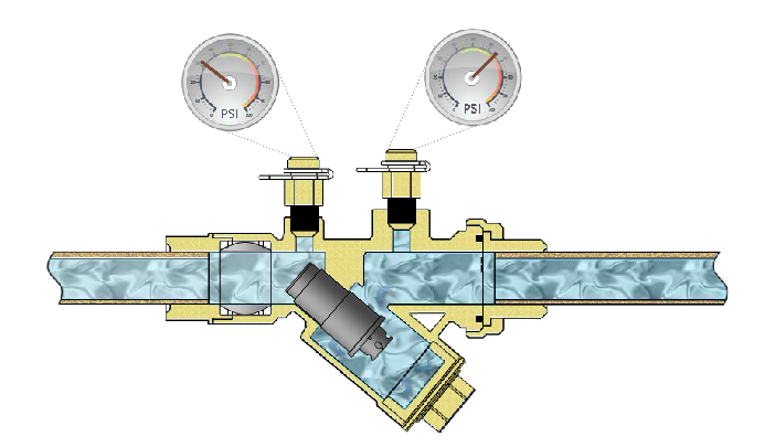
Automatic balance valves are also called flow limiting balance valves. During the balancing of the system, these valves throttle to produce the pressure drop required to reduce the flow rate down to the design flow rate. At this point the throttled automatic balance valve has the same pressure drop as the manual balance. The difference between these valves and manual balance valves shows up when systems are operating in part load with any diversity.
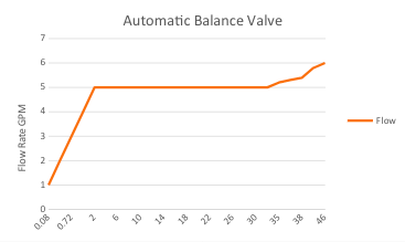
Let’s look at the curves of an automatic balance valve.
Typical Flow Limiting Balance Valve
You can see the flow limiter in the photo above with flow in the Y-axis and pressure differential in the X-axis. Below the minimum pressure drop of the valve, the valve operates as a fixed orifice just like the circuit setter. When the valve is completely compressed at the maximum differential, the valve again operates as a fixed orifice. A valve with a range of 2 – 32 PSIG will maintain the flow rate between 5 feet and 73 feet of pressure difference and adjust to maintain that flow rate. Assume the valve is factory set at 1 GPM. If the valve is throttled to 8 feet of differential, the flow rate will be 1 GPM. If the pressure available across the valve drops to 3 feet, the valve will open and the flow rate will remain 1 GPM. It is a dynamic balance valve. This provides an advantage and a disadvantage.
Automatic Flow Limiting Balance Valves: Advantages and Disadvantages
ADVANTAGES:
- Able to reduce the pressure drop at design flow rate in response to a drop in pump speed. Less of a miss in variable speed systems.
- It is not a flow meter so it does not need straight lengths of pipe upstream and downstream.
- High repeatability and 5% accuracy and in stock at R. L. Deppmann.
DISADVANTAGES:
- Normally, each valve is manufactured for a specific flow rate so the contractor has to make sure they are in the right place. The exception to this is the B&G Flow Setter II which has an advantage of dialing in the specific flow rate on the job.
- It is not a flow meter so the balance contractor can only read the pressure drop.
- The valve will start to open as the control valve closes so you lose some control valve stroke.
Automatic Flow Limiting Balance Valves and Pressure Ranges
When selecting the correct valve for the hydronic system, the pressure range is important. Start by looking at the type of system. You can calculate the exact number but a good “close enough” rule of thumb is: a direct return system will see close to the entire pump head across the closest terminal unit. Take the scheduled pump head in PSIG and make sure that pressure differential is in the range of the valve. It is okay if it is all the way at the end of the range.
The balance valve pressure drop for the design pump head should be the minimum value of the pressure range converted to feet of head. This will be more pressure drop than the 1 foot default we use for manual balance valves.
Next week, the R. L. Deppmann Monday Morning Minutes will show how the automatic flow limiting balance valve solves a big problem in variable speed systems with diversity.
Discover more on this Series: Balancing HVAC Hydronic Systems:
Balancing HVAC Hydronic Systems: Flow Tolerance (Part 1)
Balancing HVAC Hydronic Systems: Control Valves vs. Balance Valves (Part 2)
Balancing HVAC Hydronic Systems: Flow Measurement Valves (Part 3)
Balancing HVAC Hydronic Systems: Pressure Independent Control Valve (Part 5)


