Printer Friendly (PDF)
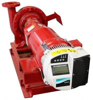
I am beginning a series on parallel staged variable speed (VS) pumps. As I write this series, it is important to understand and refer to the basic operation of a variable speed pump in a HVAC hydronic system. At the same time, one of our inside sales experts received a call from a contractor concerning the recommended minimum speed of their VS pump. He was servicing a closed system heating pump which had a minimum speed set at 5 Hz on a 60 Hz pump. My response was, whether you could do it or not, why would we ever operate at that low of a speed? This blog will address all these points.
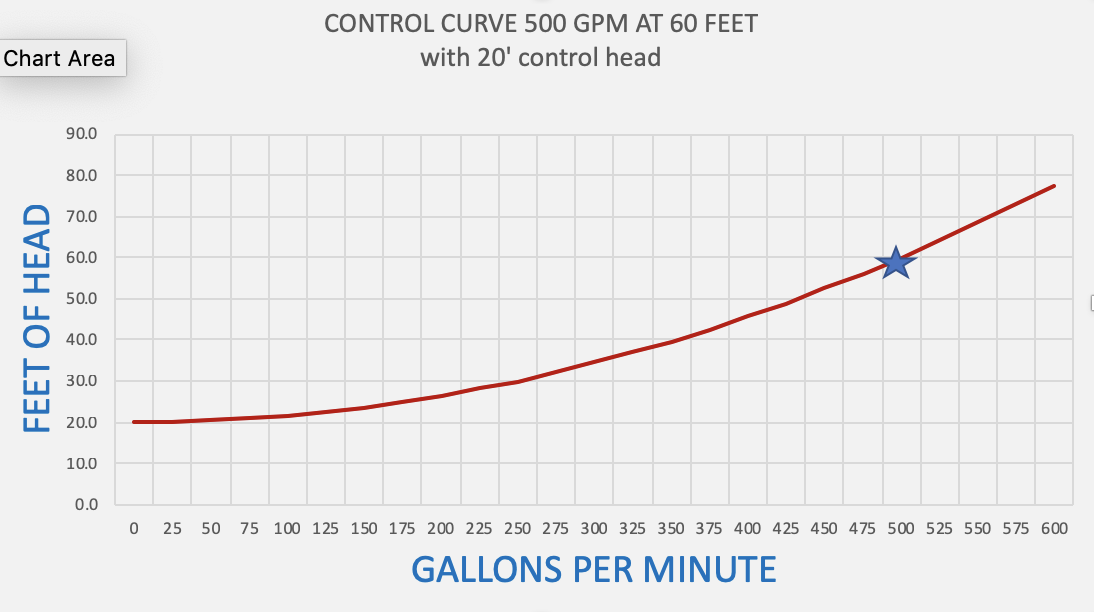
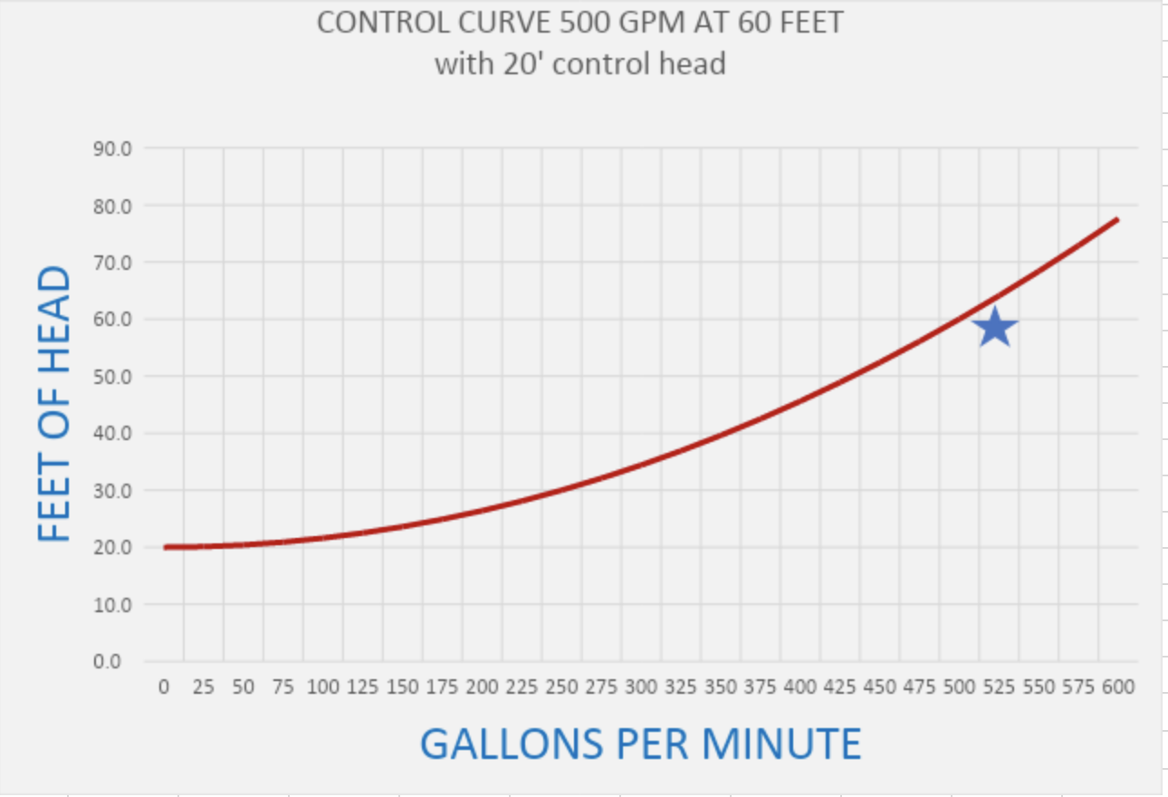
The Control Curve in Pumping
Closed hydronic pumping systems follow the pump affinity laws. The second pump affinity law says that the head varies as the square of the flow rate. This forms a system curve. The control curve is simply the system curve which starts at the control head or minimum setting of the pressure differential sensor at the farthest point in the system. This setting should be calculated, but the “rule of thumb” we use is about 10 PSIG or 23 feet.
Let’s look at an example heating system with a pump capacity of 500 GPM at 60 feet of head. The control curve looks like this:
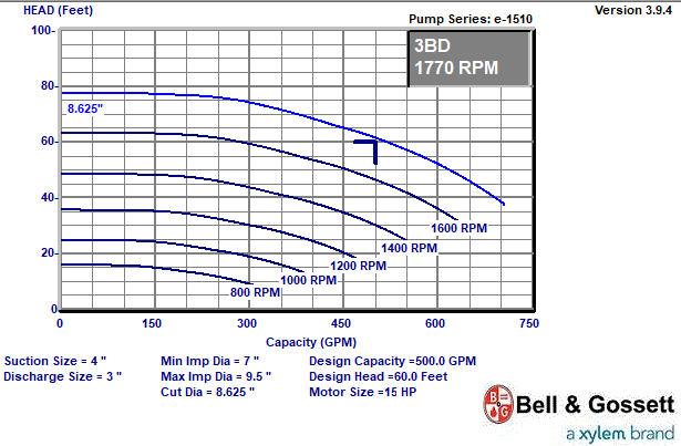
The Variable Speed Pump Curve
The variable speed pump curve is created by selecting a pump at the design condition and a design speed which is may be the motor nameplate speed or something less. Then we show the various curves as the speed is reduced. Using our example, a curve with a trimmed impeller could look like this:
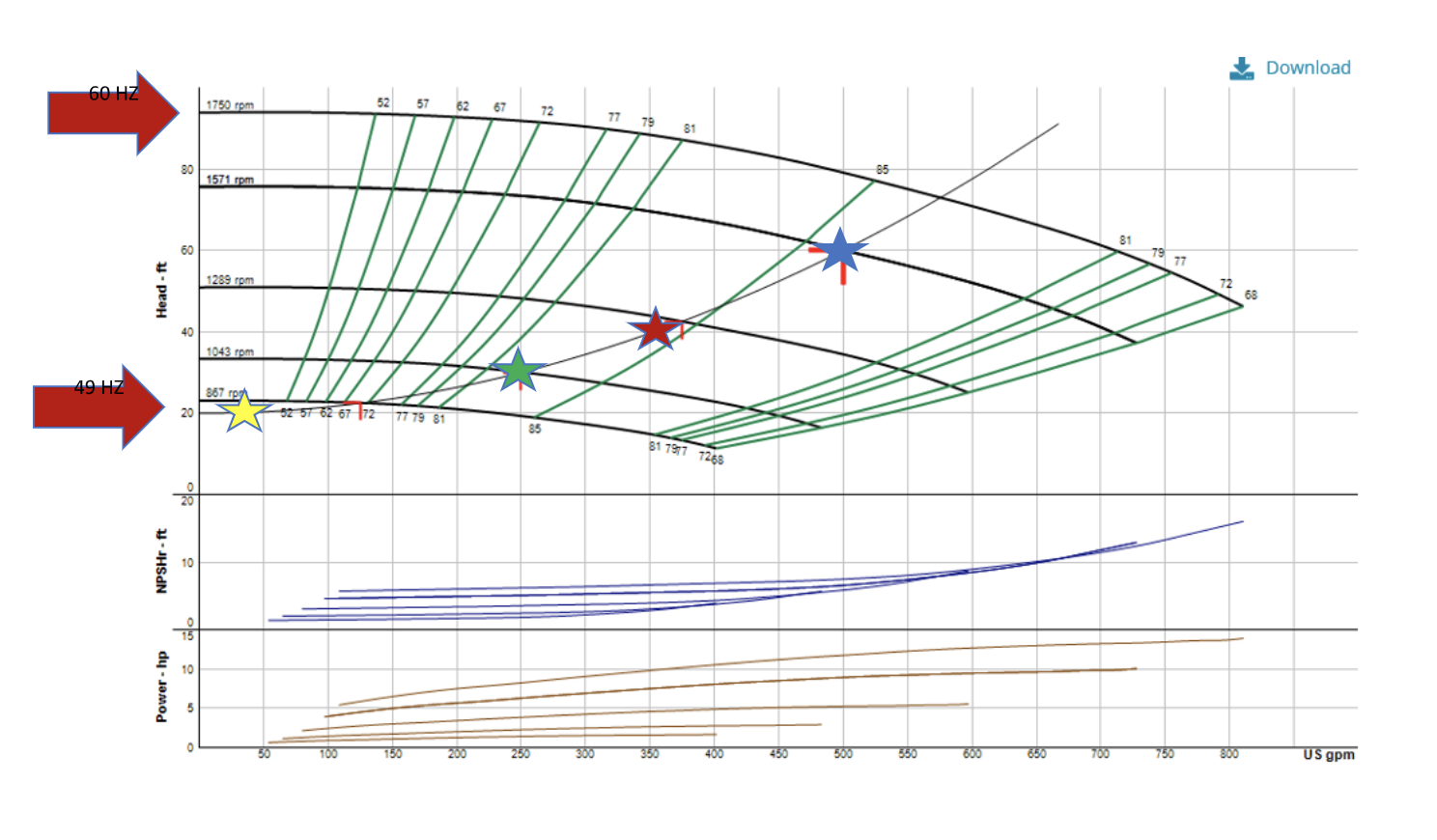
The Pump Operates at the Intersection of the System Curve and Variable Speed Pump Curve
This is important. When we place the pump in the balanced hydronic system with two-way control valves, the pump should operate at the intersection of these two curves. The control curve may float a bit based on diversity, but let’s just keep it simple for now. The two curves together look like this:
Here is the curve with full 9.5” impeller and design operation at a lower speed than the nameplate. This is done to gain some efficiency which was discussed in the HVAC Hydronic Pumps – Should I Trim the Impeller or Trim with Speed? (Part 1 OF 2)
The pump will operate at the intersection of the two curves so at 500 GPM we, obviously, operate at 60 feet and 1571 RPM or 54 Hz assuming no over-heading in the design calculations and no impeller trim. At 350 GPM, the pump will operate at 1270 RPM or 44 Hz. At 250 GPM the operation will be at 1043 RPM or 36 Hz. At the minimum boiler flow of 35 GPM, the pump will be at 800 RPM 0r 28 Hz. For this pump to operate at 5 Hz, the control head would have to be almost 0 feet. If you understand control head, this would be almost impossible. Hopefully, this answers the operational question I posed in the introduction.
This pump is operating at the minimum flow and control head at 28 Hz. It will never get to the 20 Hz minimum we normally recommend for the motors used in our industry. In 99.99% of the systems, you will never operate at 20 Hz. In 100% of the systems, you would never operate at 5 Hz. A pump operating that low in a hydronic heating system would have to be ridiculously oversized. At that low speed, the motor and VFD efficiencies are tanking. Hope this answers the contractor’s question mentioned in the introduction.
Now the next article will look at parallel pumping.