Last week I featured the ECM High-Efficiency Smart Circulator Pump used in a secondary application. This week the R.L. Deppmann Monday Morning Minutes continues to look at the application of ECM High-Efficiency Smart Circulator Pumps, applied to the primary loop of a variable speed primary-secondary hydronic heating or cooling system.
The Challenge with Primary/Secondary Systems Today
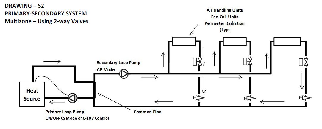
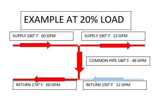
Secondary pumps serve the terminal units while the primary pump serves the boiler, chiller, or another source of heating or cooling. Most larger secondary systems have two-way control valves and the pump is variable speed. Often the primary pump is constant speed to match the constant flow requirement of the boiler or chiller. Having a system with a constant flow primary pump and a variable flow secondary pump does introduce some challenges. Look at the diagram below and let’s assume the primary pump is a constant flow.
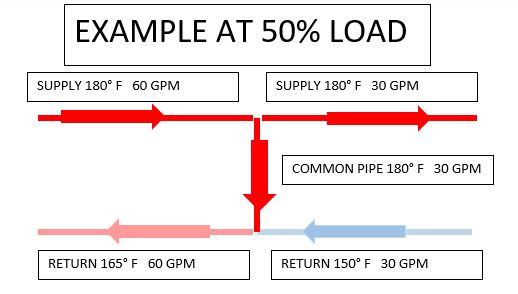
As the flow rate in the secondary loop drops below the primary flow rate, mixing occurs in the return to the boiler. This mixing will cause the boiler to turn down. Once the boiler drops to its lowest firing rate or turndown, the boiler will start to cycle which will result in wasted energy. The prudent designer will recognize this by selecting a properly sized boiler as well as a number of boilers to operate. There is another issue to be concerned with and that is temperature. Let’s look at an example.
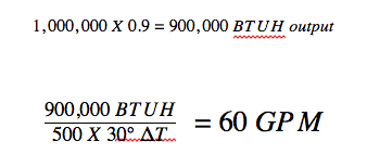
Let’s assume we have a one million BTUH boiler with a 5:1 turndown ratio and an exact load match in the secondary circuit with a 30°F ΔT system design temp of 170°F to 140°F.
What happens as the flow rate drops in the secondary circuit? As the secondary load drops, the mixing in the common pipe raises the return temperature to the boiler. Eventually, there could be issues with the boiler outlet temperature bouncing off the high limits.
Using B&G Ecocirc® -XL ECM Smart Circulator Pumps in Primary Hydronic Systems
These function in two different ways, though the application is identical: most receive a 0-10V signal from the boilers indicating what speed the boiler wants the pump to run (Laars Vari-Prime, for example). The boiler itself is determining this speed based on the delta T, it is sensing from Supply and Return. The other way this pump can function as a variable primary pump is to run it in delta T mode. In delta T mode the B&G pump is using the internal temperature sensor inside the pump, and a remote temperature sensor on the other line. The pump will speed up and slow down to maintain the delta T that is programmed into it. Most boiler manufacturers prefer to have control of this pump, so let’s look at that application.
B&G Ecocirc-XL with 0-10 Vdc Signal Electrical *
The electrical diagram is the same as other applications.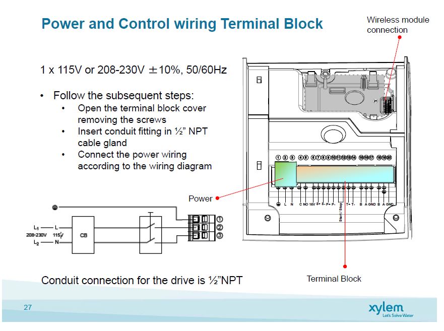
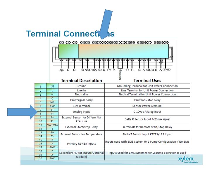
Control wiring analog signal 0-10 Vdc is wired to terminals 7 and 8.
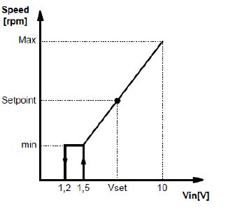
Sequence of operation: Primary Heating/Cooling Pump (insert tag) shall be enabled by a call for heat/cool (enabling the start-stop contacts 11-1 through a remote relay). The pump speed shall be varied through the analog output signal from the boiler controller. The pump shall be at full maximum speed at 10 Vdc and at minimum speed at 1.5 Vdc. The pump shall turn off at 1.19 Vdc. Fault indication will be shown on the pump and may enable an analog input; BMS fault indicator thought terminals 4-5 if shown in documents.
*Always read the complete installation and operation manual before beginning any work.*

