In this Service Tip of the Month, we will be discussing and demonstrating the operation of reading, adjusting, and setting a Bell & Gossett Balance Valve. The example we are using today is a manual balance valve across a heating coil.
The Bell & Gossett (B&G) balance valve was found to be in the 100% open position. The coil associated with the B&G balance valve was loud (velocity noise) and had difficulty maintaining the condition space. We found the blueprints to the building and quickly discovered the required design flow for this heating coil was 11GPM. This became the catalyst we needed to read the flow, adjust the B&G Circuit setter, and set the valve to the design flow of 11GPM.
Setting a Bell & Gossett Balance Valve
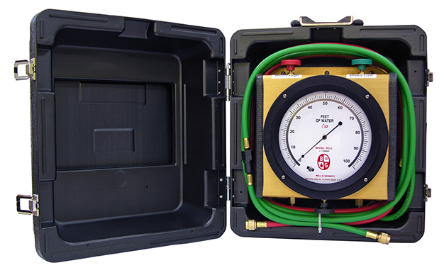
We will need a few industry tools to walk through this exercise. We will need a Bell & Gossett RO-1-60 readout meter. All readout kits feature a compound gauge that reads in feet of water and PSI and are equipped with hoses, readout probes, carrying case, and Circuit Setter Balance Valve calculator.
Now that we have everything to take a reading across the valve we will demonstrate how to properly connect and take readings on the manual balance valve from the high side and low side integral test ports of the balance valve.
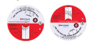
We will then calculate the differential between the high and low side test ports of the B&G manual balance valve. When using this differential on B&G Circuit Setter Balance Valve Calculator, it will give you the actual flow across that balance valve.
In this case, the first reading taken in the 100% open position was 33GPM. This reading is much higher than the desired 11GPM design flow rate.
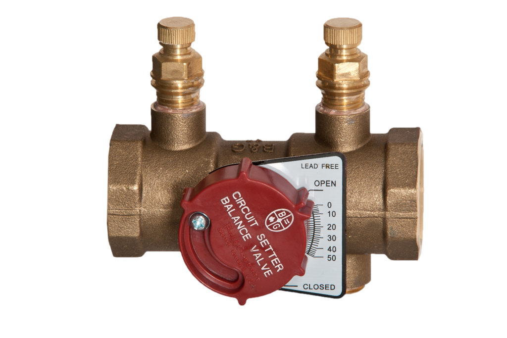
We will begin to adjust the balance valve by closing or increasing the percentage closed on the valve. As we close the valve, we will take multiple readings across the balance valve to close or lower the differential between the high and low side of the valve. Once we have achieved the 11GPM design flow rate across the valve. We will disconnect the hoses and adjust the memory stop on the valve. In this example, it was set at 15% closed to achieve the design GPM.
This concludes the exercise of reading, adjusting, and setting our Bell & Gossett manual balance valve.
Required Tools
Example of B&G R0-1-60 Readout Kit:
Example of the Circuit Setter Balance Valve Calculator:
Example of the Circuit Setter Balance Valve:
Please contact R.L. Deppmann for any questions or your Bell & Gossett needs.
Check out similar content: Flow Meter and Balance Valve Installation – Minimum Pipe Diameters for Installation