A customer recently called us about an unusual occurrence in a closed hydronic cooling system for an ice rink. The system was filled using a …

A customer recently called us about an unusual occurrence in a closed hydronic cooling system for an ice rink. The system was filled using a …

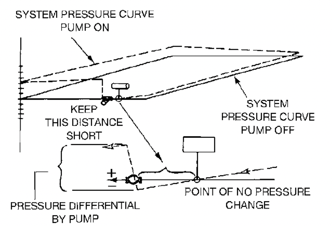
Can we pump into the point of no pressure change in a closed hydronic system? We gathered feedback on the proposed system by a local …
We are gathering input from the last R. L. Deppmann Monday Morning Minutes asking for your feedback on the potential to “not follow the rules.” …
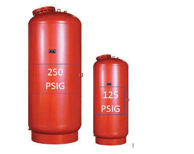
We often design system after system and designate the sizing of expansion tanks to the newest employee on the team. It is just a matter …
There is a constant flow of hydronic system design questions coming into R. L. Deppmann Company. Sometimes the questions are about complicated hydronic, steam, or …
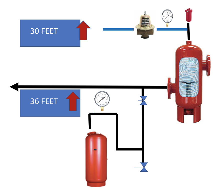
Part 2 of this series on expansion tank locations showed the expansion tank in a high-rise hydronic system located at the top of the system. …
Where should the hydronic expansion tank be in a tall high-rise hydronic system design? In part 1 of this article, I identified the size and …
We received an interesting question from an Ohio engineer working on the renovation of a 30-story high-rise hydronic heating system. This engineer was looking out …
The cold fill pressure setting in a closed hydronic heating or cooling system is still one of the key problems uncovered when our customer service …
I recently visited a school mechanical room and was asked about the relationship between the makeup pressure reducing valve setting and the expansion tank pressure …