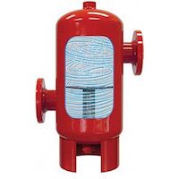
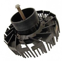
R. L. Deppmann is offering another series of seminars, this fall, which are centered on “Energy Savings and ASHRAE 90.1 and 189.1 standards”. During a couple of the first 7 seminars, the question of the air separation location sparked a short discussion. Let’s review the response in this Monday Morning Minute.
Strategies for Water Use Efficiency – Cooling Tower Selection – Part V
Today’s building owner’s have many opportunities to improve water use efficiency. ASHRAE Standard 189.1 identifies a few areas to focus on reducing water use specific to cooling towers. The last four issues of Deppmann’s Monday Morning Minutes has discussed specific strategies to improve water use efficiency using current Cooling Tower and Advanced Water Treatment technology advancements in design. [Read more…]
Strategies for Water Use Efficiency – Cooling Tower Selection – Part IV
Most new chillers can now handle variable flow through the condenser providing many opportunities for operational savings. As the cooling tower is an integral part of this system, it is important to understand the effect of flow rate changes and how to insure your cooling tower can provide optimal savings while operating [Read more…]
Strategies for Water Use Efficiency – Cooling Tower Selection – Part III
In this issue, we will discuss the changing requirements specific to “cycles of concentration” in cooling tower applications. In addition, we will review the effect of increasing cycles of concentration and provide solutions to improving these results. ASHRAE Standard 90.1-2010 code change effective 10.18.2013 states [Read more…]
Strategies for Water Use Efficiency – Cooling Towers – Part II
In this issue, we will discuss blow down and cycles of concentration. In addition to water emissions caused by evaporation and drift, cooling towers require blow-down to control the levels of dissolved minerals re-circulated in the cooling tower. These losses are offset or balanced by make up water to both maintain the level of water in the tower and more importantly, [Read more…]
Strategies for Water Use Efficiency – Cooling Tower Selection – Part 1
Open loop evaporative type Cooling Towers by design create emissions of evaporation and drift. Drift emissions from open-loop evaporative type cooling towers are unavoidable. Stand next to a conventional cooling tower and it feels like you might be taking a shower. The amount of drift can vary depending on tower design and will include any water treatment added (chemicals). [Read more…]
A Great Way to Fill the Piping Systems – Cooling Tower Pumps and Piping – Part 9
The Xylem Bell and Gossett manual TEH-1209 has a great detail for filling the tower water system piping. Many times the cooling tower pump is used to take water from the tower pan and fill the condenser and piping system. This can lead to pump problems due to the large flow rate of the pump compared with…
Pump Suction Piping Rules – Cooling Tower Pumps and Piping – Part 8
Traditional hydronic piping system designers use tools such as the Xylem Bell & Gossett System Syzer for pipe sizing. You may find this program at http://completewatersystems.com. Tower manufacturers, the Hydraulic Institute (HI), and Bell and Gossett all suggest lower velocity for pipe selection in cooling tower pump suction piping. Bell and Gossett has several pipe sizing suggestions…
Pump Suction Piping Rules – Cooling Tower Pumps and Piping – Part 7
This week we continue our suggestions for tower pump suction piping. In order to minimize problems with air, noise, and NPSH at the tower pump, Bell and Gossett recommends you try to keep high pressure drop devices out of the suction piping and also keep the velocity low. Let’s examine high pressure drop device this week.
Pump Suction Piping Rules – Cooling Tower Pumps and Piping – Part 6
Over the last several weeks we discussed the feared NPSH and showed it is rarely an issue at design conditions. More often than not, noise and pressure problems are caused by air in the suction piping system. The suction pipe, in many cooling pumping systems, is under very little pressure. In fact, the suction of the pump could be under a vacuum.


