Printer Friendly (PDF)
In the last Monday Morning Minutes post, we explored motor and drive efficiency at part load conditions as a possible reason for the rule of thumb favoring the use of 50%-50%-50% staged pressure booster pumps over 100%-100% design.
We’re exploring the following questions:
- Why do pressure boosters with more lift than friction favor a 50%-50%-50% system?
- Why do pressure boosters with relatively constant suction pressures favor a 50%-50%-50% system?
Parallel Pumping Efficiency
Last week we introduced the Input Horsepower as the brake horsepower divided by motor and drive efficiency, shown as:
IHP = (GPM X HEAD )/ (3960 X PUMP EFFICIENCY X MOTOR EFFICIENCY X DRIVE EFFICIENCY)
So, why do pressure booster systems with higher control head favor a parallel pumping arrangement?
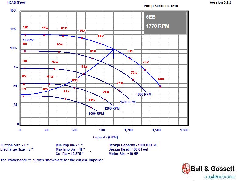
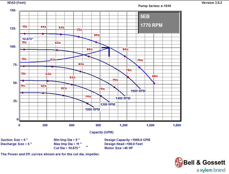
The two curves below are the same pump rated 1000 GPM at 100 feet and 40 HP. The difference is the control curve. The control head on the left side is 40 feet and the control head on the right is 80 feet. When we plot a variable speed pump curve, there are constant efficiency points as the speed drops. You can see that the control curve on the left approximately follows the 84% efficiency points. The control curve on the right crosses many efficiency points because it’s not as steep. In pumping systems with higher control heads, we are better served by 2 pumps in parallel.
Plumbing Pressure Boosters Tend to Operate at Lower Flows More Often
This fact, coupled with the control curve discussion above and the motor/drive efficiency discussion from the January 18, 2016 MMM, result in more energy savings for 50%-50%-50% pressure booster pumping systems than 100%-100% when control heads remain high as a percentage of total pumping head.
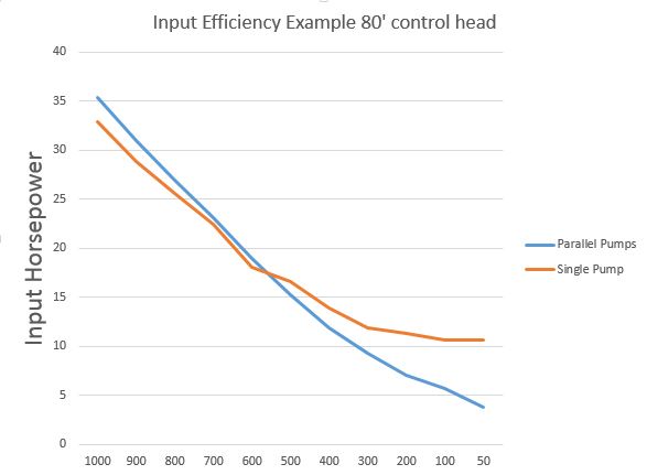
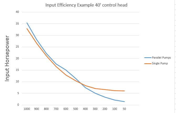
The curves below show the input horsepower for the pump curves with 1000 GPM at 100 feet. When this pumping system operates below 50% of the design flow rate, the parallel pumping systems are more efficient. In addition, if the control head is high, even more energy is saved with the parallel pumping system.
Let’s repeat our rules of thumb for pressure boosters from part 5 of this MMM series:
- Rule of thumb: If the inlet suction pressure varies by less than 50% between lowest pressure and normal pressure, a 50%-50%-50% system will be more energy efficient. In other words, if the suction pressure is fairly constant, a parallel system will be more energy efficient.
- Rule of thumb: If the discharge pressure required at low flow is greater than 75% of the design maximum discharge pressure, a 50%-50% system will be more energy efficient. In other words, a tall building with low friction losses favors a 50%-50%-50%.
R. L. Deppmann is the Bell and Gossett (a Xylem brand) representative for Michigan and northern Ohio. B&G manufacturers pressure booster systems in all price ranges, depending on the features your client needs. Our engineers are ready to assist you and answer any questions.
Check out the rest of the series!
Part 1: Parallel Pumping in Condenser Applications (Part 1)
Part 2: Parallel Pumps in Condenser Applications: Limiting the Flow Rate (Part 2)
Part 3: Parallel Pumping in Condenser Applications: Automatic Differential Pressure Control (Part 3)
Part 4: Parallel Pumping with Unequal Condensers (Part 4)
Part 5: Parallel Pumping: 2-Position Control Valves on Multiple Cooling Towers (Part 5)