Printer Friendly (PDF)
Steam flash tanks provide a valuable service in medium and high-pressure condensate return systems. The last R. L. Deppmann Monday Morning Minutes (MMM) article described the piping of condensate flash tanks when venting to atmosphere. The loss of hundreds of pounds per hour (PPH) of flash steam may seem wasteful. How can the engineer capture this steam and reclaim the energy?

Vertical Flash Tank Steam Reclaim.
In general, flash tanks in HVAC applications capture low-pressure flash steam created in the flash tank and inject it into a low-pressure system. To do this properly, the flash tank requires a different set of trim and piping than used with a vented flash tank. The engineer must review the use of the medium or high-pressure steam and the resulting condensate compared with the use of low-pressure steam. Do they operate simultaneously? If there is a use for the steam while it is flashing, the engineer may use a direct heat reclaim method. Let’s look at a direct reclaim example.
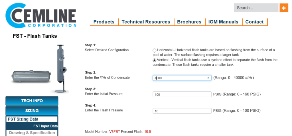
In the example below, a Cemline model V8FST flash tank was selected by the online sizing program.
Direct Flash Steam Recovery
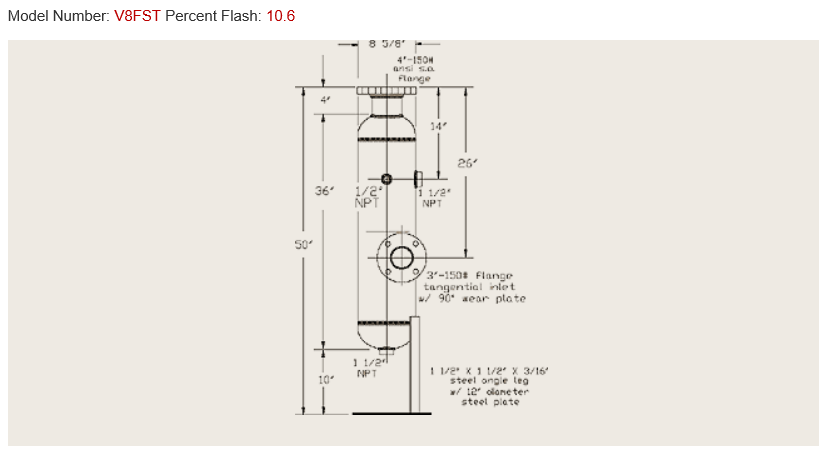
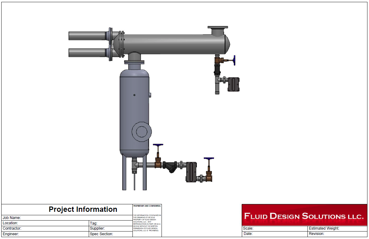
Vertical flash tanks require the same specification options identified in the previous R L Deppmann Monday Morning Minute. These items are ASME pressure vessel label, tangential inlet with wear plate, and legs or clips to install them. The flash tank drawing is shown below.
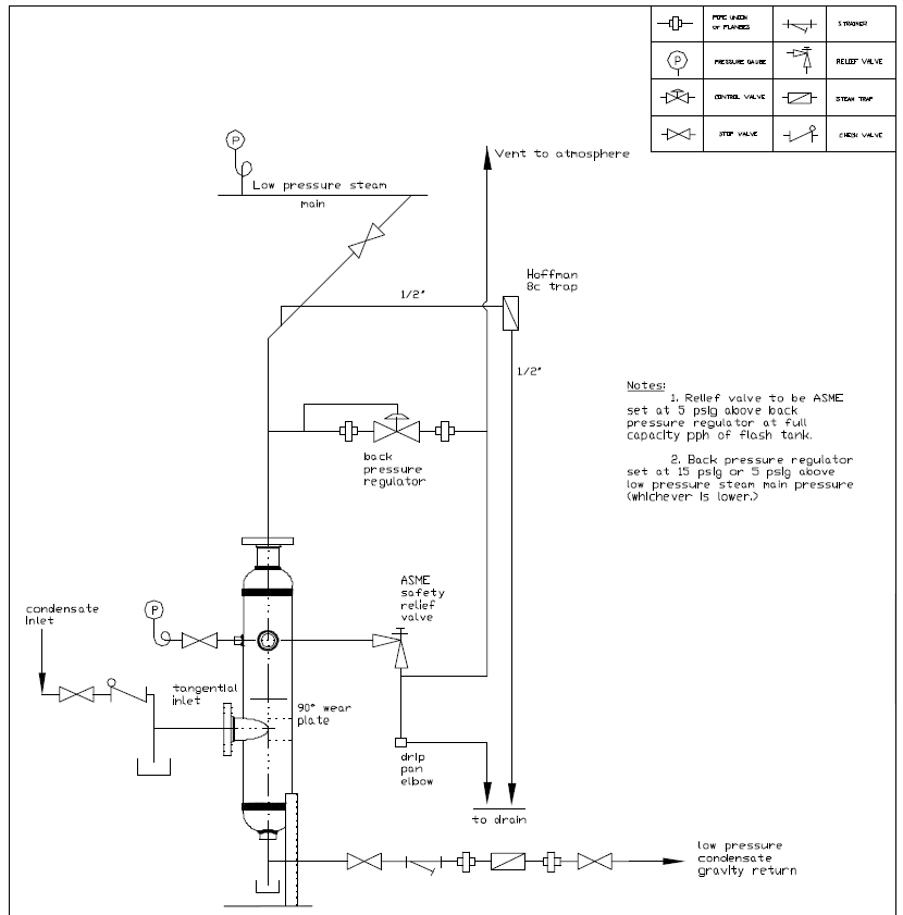
The piping detail when capturing the flash steam is shown below.
Flash Tank Back Pressure and Relief Valves.
The low-pressure steam is created in the flash tank and connected to the low-pressure steam system for recovery. The back pressure valve assures that the steam pressure does not get too high. In our example, the steam flash pressure is 10 PSIG so the back pressure valve is set at 15 PSIG or 5 PSIG above the required pressure.
The ASME pressure relief valve is set at 5 PSIG above the back pressure valve or 20 PSIG in this example. The capacity encompasses the full capacity of the flash tank. The example using the Cemline V8FST has a maximum capacity of 6000 PPH even though the example load is 4000 PPH.
The back pressure valve sets the useful pressure while the relief valve protects this system in case something goes wrong.
The Hoffman 8C thermostatic trap is used as an air vent.
Indirect Flash Steam Recovery
If the high-pressure condensate generation does not match a low-pressure steam need, an indirect method of recovery may be a better option. In this case, the flash steam is sent to a convertor or heat exchanger and the steam is used to preheat another water system. The water may be boiler feed makeup, hydronic heating system returns, or even domestic potable water. If a potable water application is applied, the heat exchanger should be double wall per code.
Next week, the R L Deppmann Monday Morning Minutes begins a new series on hydronic pumping.