 The R. L. Deppmann Monday Morning Minutes will look at near pump piping over the next several weeks. Let’s start by looking at pipe sizing and the ASHRAE 90.1-2010 & 2013 pipe sizing standards. Decades ago, your grandfather engineer used a lot of very safe rules of thumb about pump and pipe sizing.
“I always pick pumps with a discharge size that matches the pipe size.”
“My standard is to pick a pump at 40% of end of curve and I’ve never had a problem.”
“Pick your pipe at 2 ft. /100 and the heating pump will always have 30 feet of head.”
There are many unusual sizing tips out there.
Today’s young graduating HVAC engineer is tossed into the design chair without the 10 years of “starting” experience their grandfather had. Today’s HVAC engineer:
- has variable volume – variable speed systems instead of constant flow three-way valve systems.
- is more concerned with energy cost vs. first cost vs. standards vs. time allowed for design.
- has a lot more on their plate from the day they start.
How do traditional pipe sizing and the new Michigan Energy Code clash?
The Michigan Energy Code and Smaller Flanged Pipe in Chilled Water System
The current Michigan Energy Code is based on the ASHRAE 90.1-2013 standard. Section 6.5.4.6 explains the effects of pipe sizing on chilled water and condenser water systems. The pipe sizing rules are listed in the table 6.5.4.6. The sizing is based on whether it is variable volume or constant volume and the number of hours it will run. Let’s use the Bell & Gossett System Syzer to show how the run hours affect the pipe size. Let’s just look at 4” pipe as an example.
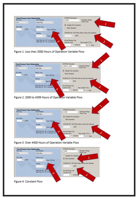
Here are screenshots from the B&G System Syzer program. This program gives a lot of information, but for today let’s focus on the maximum flow rate based on the number of run hours.
In this example, we can see in Figures 1 through 3 that the maximum flow rate for a variable speed chilled water system varies from 320 GPM to 530 GPM. A constant flow condenser system shown in Figure 4 has a maximum flow rate of 210 GPM regardless of time. This is quite a difference from the previous System Syzer recommendation of 170 to 280 GPM. This is in the energy code in Michigan as well as many other states. It is just a matter of time until it reaches the code in our Ohio territory.
Watch the Pressure Drop Per Hundred Up to 4” Size!
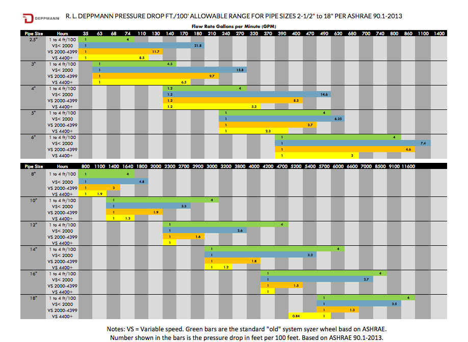
The pressure drop per 100 feet is much higher than the older standard. The pressure drop allowed in the variable flow system ranges from 5.5 ft./100 to over 14 ft./100. The pressure drop in the constant speed system tops out at a lower 2.5 ft./100. Clearly, the reasoning behind this is that we will rarely be at 100% design in a variable speed system.
The net result for the engineer that uses this table for variable speed systems is a substantial amount of savings in piping costs. The offset is much larger pump heads and installed horsepower.
In variable flow systems, you can use a larger pipe if that is your office standard. Ultimately, someone will use the smaller pipe allowed by code. If you do decide to use the smaller pipe with higher pressure drop, remember that the code says you must perform the pump head calculations. Be diligent in your calculation. With friction losses this high, it will not take much of a miss to be short of pump head or horsepower.
Watch the Pressure Drop Per Hundred Over 4” Size!
Once the pipe size gets over 4”, there is another challenge to older standards of sizing pipe. I created the chart below using the ASHRAE 90.1-2010 table. You will notice in the larger pipe for variable flow, variable speed systems over 4400 hours of operation, the pressure drop per 100 feet is well below the old standards. If you use the 4 feet per 100 standard for the larger pipe sizing, you will exceed the maximum allowed by code. In this case, the pipe cost will skyrocket while the pump head and horsepower will be reduced. Click here for an expanded printable chart.
The Exception to the Table for Pipe Sizing
There is an exception #1 in the ASHRAE standard. If the pipe is not in the “critical circuit,” the designer may exceed the maximum GPM or velocity listed. Said another way, if the pipe is not in the “longest run” that determines the pump head, the flow may be exceeded.
As we look at the piping near the pump, it is obvious that the pressure drop from the pipe and equipment at the pump is part of the critical circuit. I will expand the chart and use this information in the next few R.L. Deppmann Monday Morning Minutes. At the end of this short series, you may look forward to some CAD and Revit ready tools to help your design while reducing the hours you spend on project design.

